Nissan Pathfinder (2010 year). Manual - part 467


  Index      Manuals     Nissan Pathfinder (2010 year) - Service and Repair Manual


Search            copyright infringement  


Content      ..     465      466      467      468     ..


Nissan Pathfinder (2010 year). Manual - part 467


INTERIOR ROOM LAMP CONTROL CIRCUIT

INL-19

< COMPONENT DIAGNOSIS >

C

D

E

F

G

H

I

J

K

M

A

B

INL

N

O

P

INTERIOR ROOM LAMP CONTROL CIRCUIT

Description

INFOID:0000000005255045

Controls the following interior room lamps (ground side) by PWM signal

• Front room/map lamp assembly

• Personal lamp 2nd row (with personal lamp 2nd row)

• Room lamp 2nd row (without personal lamp 2nd row)

NOTE:

PWM signal control period is approximately 250 Hz (in the gradual brightening/dimming).

Component Function Check

INFOID:0000000005255046

CAUTION:

 Before performing the diagnosis, check that the following is normal.

• Battery saver output/power supply

• Front room/map lamp bulbs

• Personal lamp 2nd row bulbs (with personal lamp 2nd row)

• Room lamp 2nd row bulbs (without personal lamp 2nd row)

1.

CHECK INTERIOR ROOM LAMP CONTROL FUNCTION

CONSULT-III

1. Switch the map lamp switch to DOOR.

2. Turn ignition switch ON.

3. Select “INT LAMP” of BCM (INT LAMP) active test item.

4. While operating the test item, check that each interior room lamp turns ON/OFF (gradual brightening/dim-

ming).

Is the inspection result normal?

YES

>> Interior room lamp control circuit is normal.

NO

>> Refer to 

INL-19, "Diagnosis Procedure"

.

Diagnosis Procedure

INFOID:0000000005255047

Regarding Wiring Diagram information, refer to 

INL-25, "Wiring Diagram"

.

1.

CHECK INTERIOR ROOM LAMP CONTROL OUTPUT

CONSULT-III

1. Turn ignition switch ON.

2. Select “INT LAMP” of BCM (INT LAMP) active test item.

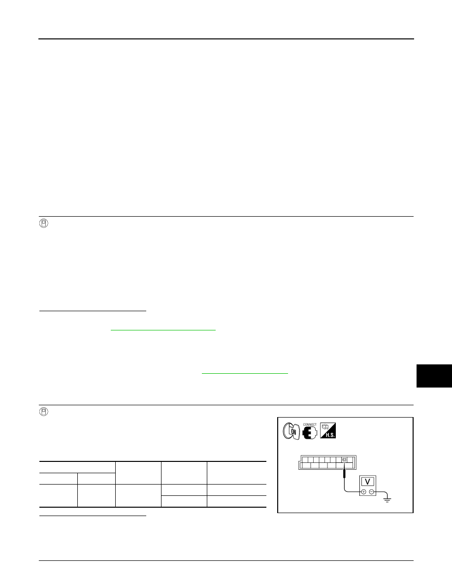
3. While operating the test item, check voltage between BCM har-

ness connector M20 terminal 63 and ground.

Is the inspection result normal?

YES

>> Interior room lamp control circuit is operating normally.

Fixed ON>>GO TO 3

Fixed OFF>> GO TO 2

2.

CHECK INTERIOR ROOM LAMP CONTROL OPEN CIRCUIT

ON

: Interior room lamp gradual brightening

OFF

: Interior room lamp gradual dimming

(+)

(-)

INT LAMP

Voltage

Connector

Terminal

M20

63

Ground

ON

0V

OFF

Battery voltage

ALLIA0410GB

2010 Pathfinder

INL-20

< COMPONENT DIAGNOSIS >

INTERIOR ROOM LAMP CONTROL CIRCUIT

1. Turn ignition switch OFF.

2. Disconnect BCM connector M20, personal lamp 2nd row connector (with personal lamp 2nd row) or room

lamp 2nd row connector (without personal lamp 2nd row) and front room/map lamp connector.

3. Check continuity between BCM connector M20 terminal 63 and

interior room lamp connectors.

Is the inspection result normal?

YES

>> Check interior room lamps for an open. If OK, replace

BCM. Refer to 

BCS-59, "Removal and Installation"

. If

NG, replace interior room lamp. Refer to 

INL-65,

"Removal and Installation"

.

NO

>> Repair the harness or connectors.

3.

CHECK INTERIOR ROOM LAMP CONTROL SHORT CIRCUIT

1. Turn ignition switch OFF.

2. Disconnect BCM connector M20, personal lamps 2nd row con-

nector (with personal lamp 2nd row) or room lamp 2nd row con-

nector (without personal lamp 2nd row).

3. Check continuity between BCM connector and ground.

Is the inspection result normal?

YES

>> Check interior room lamps for a short circuit. If OK,

replace BCM. Refer to 

BCS-59, "Removal and Installa-

tion"

. If NG, replace interior room lamp. Refer to 

INL-65, "Removal and Installation"

.

NO

>> Repair the harness or connectors.

Terminal

Terminal

Continuity

Connector

Terminal

Component

Connector

Terminal

A: M20

63

Room lamp 2nd 
row (without per-
sonal lamp 2nd 
row) 

B: R12

1

Yes

Personal lamp 
2nd row (with per-
sonal lamp 2nd 
row)

C: R10

2

Front room/map 
lamp 

D: R9

2

ALLIA0648GB

Connector

Terminal

Continuity

M20

63

Ground

No

ALLIA0413GB

2010 Pathfinder

CARGO LAMP CONTROL CIRCUIT

INL-21

< COMPONENT DIAGNOSIS >

C

D

E

F

G

H

I

J

K

M

A

B

INL

N

O

P

CARGO LAMP CONTROL CIRCUIT

Description

INFOID:0000000005255048

Controls the cargo lamp (ground side) to turn the cargo lamp ON and OFF.

Component Function Check

INFOID:0000000005255049

CAUTION:

 Before performing the diagnosis, check that the following is normal.

• Battery saver output/power supply

• Cargo lamp bulb

1.

CHECK CARGO LAMP OPERATION 

CONSULT-III

1. Turn ignition switch ON.

2. Select “LUGGAGE LAMP TEST” of BCM (INT LAMP) active test item.

3. While operating the test item, check that cargo lamp turns ON/OFF.

Is the inspection result normal?

YES

>> Cargo lamp circuit is normal.

NO

>> Refer to 

INL-21, "Diagnosis Procedure"

.

Diagnosis Procedure

INFOID:0000000005255050

Regarding Wiring Diagram information, refer to 

INL-25, "Wiring Diagram"

.

1.

CHECK CARGO LAMP OUTPUT

CONSULT-III

1. Turn ignition switch ON.

2. Select “LUGGAGE LAMP TEST” of BCM (INT LAMP) active test

item.

3. While operating the test item, check voltage between BCM con-

nector M19 terminal 49 and ground.

Is the inspection result normal?

YES

>> Cargo lamp control circuit is operating normally.

Fixed ON>>GO TO 3

Fixed OFF>>GO TO 2

2.

CHECK CARGO LAMP OPEN CIRCUIT

ON

: Cargo lamp ON

OFF

: Cargo lamp OFF

Connector

Terminal

LUGGAGE 

LAMP TEST

Voltage

M19

49

Ground

ON

0V

OFF

Battery voltage

ALLIA0417GB

2010 Pathfinder

INL-22

< COMPONENT DIAGNOSIS >

CARGO LAMP CONTROL CIRCUIT

1. Turn ignition switch OFF.

2. Disconnect BCM connector M19 and cargo lamp connector.

3. Check continuity between BCM connector M19 (A) terminal 49

and cargo lamp connector R11 (B) terminal 1.

Is the inspection result normal?

YES

>> Check cargo lamp for an open. If OK, replace BCM.

Refer to 

BCS-59, "Removal and Installation"

. If NG, replace cargo lamp. Refer to 

INL-69,

"Removal and Installation"

.

NO

>> Repair harness or connectors.

3.

CHECK CARGO LAMP SHORT CIRCUIT

1. Turn ignition switch OFF.

2. Disconnect BCM connector M19 and cargo lamp connector R11.

3. Check continuity between BCM connector M19 terminal 49 and

ground.

Is the inspection result normal?

YES

>> Check cargo lamp for a short circuit. If OK, replace

BCM. Refer to 

BCS-59, "Removal and Installation"

. If

NG, replace cargo lamp. Refer to 

INL-69, "Removal and

Installation"

.

NO

>> Repair harness or connectors.

BCM

Cargo lamp

Continuity

Connector

Terminal

Connector

Terminal

M19 (A)

49

R11 (B)

1

Yes

ALLIA0418GB

Connector

Terminal

Continuity

M19

49

Ground

No

ALLIA0419GB

2010 Pathfinder

IGNITION KEYHOLE ILLUMINATION CONTROL CIRCUIT

INL-23

< COMPONENT DIAGNOSIS >

C

D

E

F

G

H

I

J

K

M

A

B

INL

N

O

P

IGNITION KEYHOLE ILLUMINATION CONTROL CIRCUIT

Description

INFOID:0000000005255051

Controls the ignition keyhole illumination (ground side) to turn the ignition keyhole illumination ON and OFF.

Component Function Check

INFOID:0000000005255052

CAUTION:

Before performing the diagnosis, check that the following is normal.

• Battery saver output/power supply circuit

• Ignition keyhole illumination bulb

1.

CHECK IGNITION KEYHOLE ILLUMINATION OPERATION

CONSULT-III

1. Turn the ignition switch ON.

2. Select “IGN ILLUM” of BCM (INT LAMP) active test item.

3. While operating the test item, check that the ignition keyhole illumination turns ON/OFF

Is the inspection result normal?

YES

>> Ignition keyhole illumination circuit is normal.

NO

>> Refer to 

INL-23, "Diagnosis Procedure"

.

Diagnosis Procedure

INFOID:0000000005255053

Regarding Wiring Diagram information, refer to 

INL-25, "Wiring Diagram"

.

1.

CHECK IGNITION KEYHOLE OUTPUT

CONSULT-III

1. Turn ignition switch ON.

2. Select “IGN ILLUM” of BCM (INT LAMP) active test item.

3. While operating the test item, check voltage between BCM con-

nector M18 terminal 1 and ground.

Is the inspection result normal?

YES

>> Ignition keyhole illumination is operating normally.

Fixed ON>>GO TO 3

Fixed OFF>>GO TO 2

2.

CHECK IGNITION KEYHOLE ILLUMINATION OPEN CIRCUIT

ON

: Ignition keyhole illumination ON

OFF

: Ignition keyhole illumination OFF

Connector

Terminal

IGN ILLUM

Voltage

M18

1

Ground

ON

0V

OFF

Battery voltage

ALLIA0420GB

2010 Pathfinder

INL-24

< COMPONENT DIAGNOSIS >

IGNITION KEYHOLE ILLUMINATION CONTROL CIRCUIT

1. Turn ignition switch OFF.

2. Disconnect BCM connector M18 and ignition keyhole illumina-

tion connector.

3. Check continuity between BCM connector M18 (A) terminal 1

and ignition keyhole illumination connector M150 (B) terminal 2.

Is the inspection result normal?

YES

>> Check ignition keyhole illumination for an open. If OK, replace BCM. Refer to 

BCS-59, "Removal

and Installation"

. If NG, replace ignition keyhole illumination. 

NO

>> Repair harness or connectors.

3.

CHECK IGNITION KEYHOLE ILLUMINATION SHORT CIRCUIT

1. Turn ignition switch OFF.

2. Disconnect BCM connector M18 and ignition keyhole illumina-

tion connector.

3. Check continuity between BCM connector M18 terminal 1 and

ground.

Is the inspection result normal?

YES

>> Check ignition keyhole illumination for a short circuit. If

OK, replace BCM. Refer to 

BCS-59, "Removal and

Installation"

. If NG, replace ignition keyhole illumination. 

NO

>> Repair harness or connectors.

BCM

Ignition keyhole illumination

Continuity

Connector

Terminal

Connector

Terminal

M18 (A)

1

M150 (B)

2

Yes

ALLIA0421GB

Connector

Terminal

Continuity

M18

1

Ground

No

ALLIA0422GB

2010 Pathfinder

INTERIOR ROOM LAMP CONTROL SYSTEM

INL-25

< COMPONENT DIAGNOSIS >

C

D

E

F

G

H

I

J

K

M

A

B

INL

N

O

P

INTERIOR ROOM LAMP CONTROL SYSTEM

Wiring Diagram

INFOID:0000000005255054

ABLWA0544GB

2010 Pathfinder

INL-26

< COMPONENT DIAGNOSIS >

INTERIOR ROOM LAMP CONTROL SYSTEM

ABLWA0545GB

2010 Pathfinder


Content      ..     465      466      467      468     ..