Nissan Pathfinder (2010 year). Manual - part 440


  Index      Manuals     Nissan Pathfinder (2010 year) - Service and Repair Manual


Search            copyright infringement  


Content      ..     438      439      440      441     ..


Nissan Pathfinder (2010 year). Manual - part 440


HA-54

< ON-VEHICLE REPAIR >

REFRIGERANT PRESSURE SENSOR

REFRIGERANT PRESSURE SENSOR

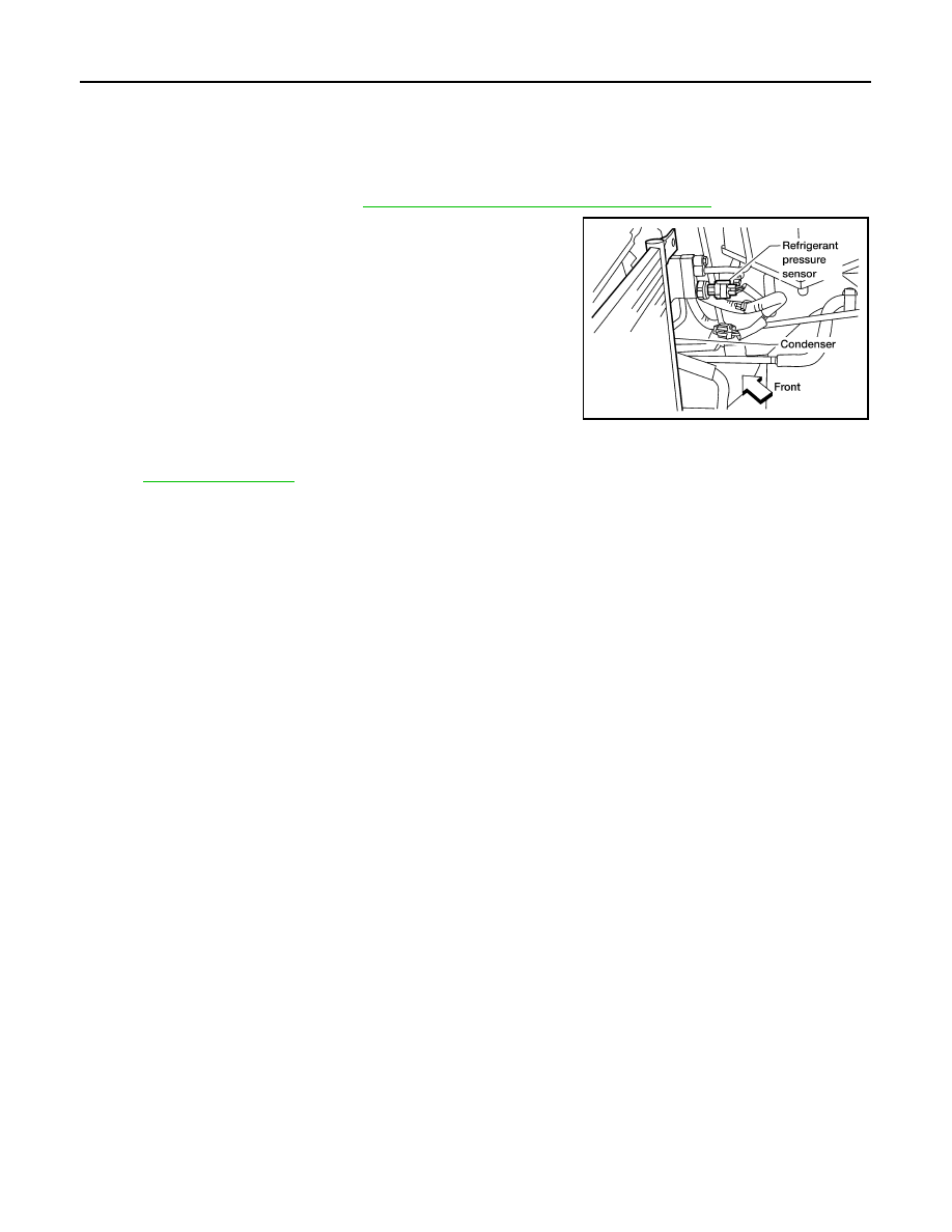
Removal and Installation for Refrigerant Pressure Sensor

INFOID:0000000005256854

REMOVAL

1. Discharge the refrigerant. Refer to 

HA-37, "HFC-134a (R-134a) Service Procedure"

.

2. Disconnect the refrigerant pressure sensor harness connector

and remove the refrigerant pressure sensor from the condenser.

CAUTION:

Be careful not to damage the condenser fins.

INSTALLATION

Installation is in the reverse order of removal.

Refer to 

HA-34, "Component"

.

CAUTION:

• Be careful not to damage the condenser fins.

• Replace the O-ring of the refrigerant pressure sensor with a new one, then apply compressor oil to it

for installation.

• After charging refrigerant, check for leaks.

LJIA0177E

2010 Pathfinder

EXPANSION VALVE

HA-55

< ON-VEHICLE REPAIR >

C

D

E

F

G

H

J

K

L

M

A

B

HA

N

O

P

EXPANSION VALVE

Removal and Installation for Front Expansion Valve

INFOID:0000000005256855

REMOVAL

1. Discharge the refrigerant. Refer to 

HA-37, "HFC-134a (R-134a) Service Procedure"

.

2. Remove the front heater and cooling unit assembly. Refer to 

VTL-18, "Removal and Installation"

.

3. Remove the front heater core and evaporator pipes grommet.
4. Remove the front expansion valve.

INSTALLATION

Installation is in the reverse order of removal.

CAUTION:

• Replace the O-rings on then front expansion valve and the A/C refrigerant pipes with new ones, then

apply compressor oil to them for installation.

• After charging refrigerant, check for leaks.

Expansion valve bolts

: Refer to 

HA-34, "Component"

.

A/C refrigerant pipe to expansion valve bolt

: Refer to 

HA-34, "Component"

.

2010 Pathfinder

HA-56

< ON-VEHICLE REPAIR >

AMBIENT SENSOR

AMBIENT SENSOR

Removal and Installation

INFOID:0000000005256856

REMOVAL

1. Remove the front grille. Refer to 

EXT-18, "Removal and Installation"

.

2. Disconnect the ambient sensor (1) electrical connector.

: Front

NOTE:

The ambient sensor is located behind the front grille, below the

hood latch.

3. Release the ambient sensor (1) clip and then remove the ambi-

ent sensor (1).

INSTALLATION

Installation is in the reverse order of removal.

AWIIA0262ZZ

2010 Pathfinder

HEATER PUMP

HA-57

< ON-VEHICLE REPAIR >

C

D

E

F

G

H

J

K

L

M

A

B

HA

N

O

P

HEATER PUMP

Removal and Installation

INFOID:0000000005256857

Heater Pump

NOTE:

Only the VQ40DE engine is equipped with a heater pump for the rear heater system.

REMOVAL

1. Partially drain the engine cooling system. Refer to 

CO-12, "Changing Engine Coolant"

 (VQ40DE).

2. Disconnect the heater pump electrical connector.
3. Disconnect the two heater hoses.
4. Remove the heater pump from the bracket securing the heater pump to the cowl top.

CAUTION:

Do not disassemble the heater pump, replace the heater pump as an assembly.

INSTALLATION

Installation is in the reverse order of removal.

CAUTION:

• The heater pump rubber mount must be fully seated on the bracket.

• Do not disassemble the heater pump, replace the heater pump as an assembly.

LBIA0414E

1.

Cowl top

2.

Heater pump electrical connector

3.

Heater pump

4.

Heater hose and clamp

5.

Heater hose and clamp

2010 Pathfinder

HA-58

< SERVICE DATA AND SPECIFICATIONS (SDS) 

SERVICE DATA AND SPECIFICATIONS (SDS)

SERVICE DATA AND SPECIFICATIONS (SDS)

SERVICE DATA AND SPECIFICATIONS (SDS)

Service Data and Specification (SDS)

INFOID:0000000005256858

COMPRESSOR

OIL

REFRIGERANT

Make

ZEXEL VALEO CLIMATE CONTROL

Model

DKS-17D

Type

Swash plate

Displacement

175.5 cm

3

 (10.7 in

3

) / revolution

Cylinder bore 

×

 stroke

30.5 mm (1.20 in) x 24.0 mm (0.94 in)

Direction of rotation

Clockwise (viewed from drive end)

Drive belt

Poly V

Name

NISSAN A/C System Oil Type S or equivalent

Capacity

With rear A/C

210 m  (7.1 US fl oz, 7.4 Imp fl oz)

Without rear A/C

180 m  (6.1 US fl oz, 6.3 Imp fl oz)

Type

HFC 134a (R-134a)

Capacity

With rear A/C

0.85 

±

 0.05 kg (1.87 

±

 0.11 lb)

Without rear A/C

0.70 

±

 0.05 kg (1.54 

±

 0.11 lb)

2010 Pathfinder

HAC-1

VENTILATION, HEATER & AIR CONDITIONER

C

D

E

F

G

H

J

K

L

M

SECTION 

HAC

A

B

HAC

N

O

P

CONTENTS

HEATER & AIR CONDITIONING CONTROL SYSTEM

AUTOMATIC AIR CONDITIONER

BASIC INSPECTION  ....................................

4

DIAGNOSIS AND REPAIR WORKFLOW  ..........

4

How to Perform Trouble Diagnosis For Quick And 
Accurate Repair  ......................................................
..

4

INSPECTION AND ADJUSTMENT .....................

5

Operational Check (Front) .........................................

5

Operational Check (Rear)  .........................................

6

FUNCTION DIAGNOSIS ...............................

8

FUNCTION INFORMATION  ................................

8

Component Part Location  .........................................

8

Symptom Table  .......................................................

11

REFRIGERATION SYSTEM  ..............................

13

Refrigerant Cycle  ....................................................

13

Refrigerant System Protection ................................

13

AUTOMATIC AIR CONDITIONER SYSTEM  .....

15

Control System Diagram  .........................................

15

Control System Description .....................................

15

Discharge Air Flow (Front)  ......................................

18

Switches And Their Control Function (Front)  ..........

19

Switches And Their Control Function (Rear) ...........

20

DIAGNOSIS SYSTEM (HVAC)  ..........................

21

CONSULT-III Function (HVAC) ...............................

21

DIAGNOSIS SYSTEM (BCM)  ............................

22

CONSULT-III Function (BCM - COMMON ITEM) ....

22

CONSULT-III Function (BCM - AIR CONDITION-
ER) ..........................................................................

23

SELF-DIAGNOSIS FUNCTION ..........................

24

A/C Auto Amp. Self-Diagnosis ................................

24

A/C and AV Switch Assembly Self-Diagnosis  .........

24

A/C System Self-Diagnosis Code Chart ..................

25

COMPONENT DIAGNOSIS  .........................

26

MODE DOOR MOTOR ......................................

26

System Description ..................................................

26

Mode Door Motor (Front) Component Function 
Check ......................................................................

27

Mode Door Motor (Front) Diagnosis Procedure  ......

27

AIR MIX DOOR MOTOR  ...................................

31

System Description ..................................................

31

Air Mix Door Motor (Driver) Component Function 
Check ......................................................................

32

Air Mix Door Motor (Driver) Diagnosis Procedure ....

33

Air Mix Door Motor (Passenger) Component 
Function Check ........................................................

36

Air Mix Door Motor (Passenger) Diagnosis Proce-
dure .........................................................................

36

INTAKE DOOR MOTOR  ...................................

40

System Description ..................................................

40

Intake Door Motor Component Function Check  ......

41

Intake Door Motor Diagnosis Procedure  .................

41

BLOWER MOTOR CONTROL SYSTEM ..........

43

System Description ..................................................

43

Front Blower Motor Component Function Check ....

44

Front Blower Motor Diagnosis Procedure ................

44

Front Blower Motor Component Inspection  .............

48

Rear Blower Motor Description ................................

49

Rear Blower Motor Component Function Check  .....

50

Rear Air Control (Front) Diagnosis Procedure #1 ....

51

Rear Air Control (Rear) Diagnosis Procedure #2 ....

52

Rear Air Control (Rear) Diagnosis Procedure #3 ....

53

Rear Air Control (Rear) Diagnosis Procedure #4 ....

56

Rear Blower Motor And Relay Component Inspec-
tion ...........................................................................

57

REAR AIR CONTROL SYSTEM .......................

59

Rear Air Control System Description .......................

59

Rear Air Control Component Function Check  .........

59

Rear Air Control (Front) Diagnosis Procedure .........

60

Rear Air Control (Rear) Diagnosis Procedure  .........

62

MAGNET CLUTCH  ...........................................

65

2010 Pathfinder

HAC-2

System Description .................................................

65

Magnet Clutch Component Function Check ...........

65

Magnet Clutch Diagnosis Procedure  ......................

65

WATER VALVE CIRCUIT ..................................

70

Water Valve Description (VK56DE) ........................

70

Water Valve Diagnosis Procedure (VK56DE) .........

70

HEATER PUMP  .................................................

72

System Description (VQ40DE)  ...............................

72

Diagnosis Procedure (VQ40DE) .............................

72

Component Inspection (VQ40DE)  ..........................

74

AMBIENT SENSOR ...........................................

75

Component Description  ..........................................

75

Ambient Sensor Diagnosis Procedure ....................

75

Ambient Sensor Component Inspection  .................

76

IN-VEHICLE SENSOR .......................................

78

Component Description  ..........................................

78

In-Vehicle Sensor Diagnosis Procedure .................

78

In-Vehicle Sensor Component Inspection  ..............

80

OPTICAL SENSOR  ...........................................

81

Component Description  ..........................................

81

Optical Sensor Diagnosis Procedure ......................

81

INTAKE SENSOR ..............................................

83

System Description .................................................

83

Intake Sensor Diagnosis Procedure  .......................

83

Intake Sensor Component Inspection  ....................

84

POWER SUPPLY AND GROUND CIRCUIT 
FOR CONTROLLER ..........................................

86

Component Description  ..........................................

86

A/C Auto Amp. Component Function Check  ..........

86

A/C Auto Amp Power and Ground Diagnosis Pro-
cedure ....................................................................
.

87

ECU DIAGNOSIS  ........................................

88

AIR CONDITIONER CONTROL  ........................

88

A/C Auto Amp. Terminals Reference Values  .........

88

Wiring Diagram  .......................................................

90

SYMPTOM DIAGNOSIS  ............................

106

AIR CONDITIONER CONTROL  ......................

106

Symptom Matrix Chart .........................................

106

INSUFFICIENT COOLING ...............................

107

Component Function Check  ..................................

107

Diagnostic Work Flow ............................................

108

Performance Chart  ................................................

110

Trouble Diagnoses for Abnormal Pressure  ...........

111

INSUFFICIENT HEATING  ...............................

115

Component Function Check  ..................................

115

NOISE ..............................................................

117

Component Function Check  ..................................

117

MEMORY FUNCTION DOES NOT OPERATE ..

119

Memory Function Check  .......................................

119

PRECAUTION ...........................................

120

PRECAUTIONS  ................................................

120

Precaution for Supplemental Restraint System 
(SRS) "AIR BAG" and "SEAT BELT PRE-TEN-
SIONER" ...............................................................

120

Working with HFC-134a (R-134a) .........................

120

Precaution for Service Equipment ........................

121

MANUAL AIR CONDITIONER

BASIC INSPECTION .................................

122

DIAGNOSIS AND REPAIR WORKFLOW ........

122

How to Perform Trouble Diagnosis For Quick And 
Accurate Repair  ....................................................

122

INSPECTION AND ADJUSTMENT ..................

123

Operational Check  ................................................

123

FUNCTION DIAGNOSIS  ...........................

125

FUNCTION INFORMATION  .............................

125

Component Part Location  .....................................

125

Symptom Table .....................................................

127

REFRIGERATION SYSTEM .............................

128

Refrigerant Cycle  ..................................................

128

Refrigerant System Protection ..............................

128

MANUAL AIR CONDITIONER SYSTEM  .........

130

Control System Diagram .......................................

130

Control System Description ..................................

130

Discharge Air Flow ................................................

132

Switches And Their Control Function ....................

132

DIAGNOSIS SYSTEM (BCM) ...........................

134

CONSULT-III Function (BCM - COMMON ITEM) .

134

CONSULT-III Function (BCM - AIR CONDITION-
ER) ........................................................................

135

COMPONENT DIAGNOSIS  ......................

136

MODE DOOR MOTOR  .....................................

136

System Description  ...............................................

136

Mode Door Motor (Front) Component Function 
Check ....................................................................

136

Mode Door Motor (Front) Diagnosis Procedure ....

137

AIR MIX DOOR MOTOR  ..................................

139

System Description  ...............................................

139

Air Mix Door Motor Component Function Check  ..

140

Air Mix Door Motor Diagnosis Procedure ..............

140

INTAKE DOOR MOTOR ...................................

143

System Description  ...............................................

143

Intake Door Motor Component Function Check ....

143

Intake Door Motor Diagnosis Procedure ...............

144

BLOWER MOTOR ............................................

146

2010 Pathfinder

HAC-3

C

D

E

F

G

H

J

K

L

M

A

B

HAC

N

O

P

System Description  ...............................................

146

Front Blower Motor Component Function Check ..

146

Front Blower Motor Diagnosis Procedure  .............

147

Front Blower Motor Component Inspection ...........

150

MAGNET CLUTCH ...........................................

153

System Description  ...............................................

153

Magnet Clutch Component Function Check  .........

153

Magnet Clutch Diagnosis Procedure .....................

153

INTAKE SENSOR  ............................................

157

System Description  ...............................................

157

Intake Sensor Diagnosis Procedure ......................

157

Intake Sensor Component Inspection ...................

158

POWER SUPPLY AND GROUND CIRCUIT 
FOR CONTROLLER  ........................................

160

Component Description .........................................

160

Front Air Control Component Function Check  ......

160

Front Air Control Power and Ground Diagnosis 
Procedure ..............................................................

160

ECU DIAGNOSIS .......................................

162

AIR CONDITIONER CONTROL .......................

162

System Description  ...............................................

162

System Operation  .................................................

162

Front Air Control Terminals Reference Values  .....

163

Wiring Diagram ......................................................

165

SYMPTOM DIAGNOSIS  ............................

172

AIR CONDITIONER CONTROL ......................

172

Symptom Matrix Chart .........................................

172

INSUFFICIENT COOLING  ..............................

173

Component Function Check  ..................................

173

Diagnostic Work Flow ............................................

174

Performance Chart  ................................................

176

Trouble Diagnoses for Abnormal Pressure  ...........

177

INSUFFICIENT HEATING ...............................

181

Component Function Check  ..................................

181

NOISE ..............................................................

183

Component Function Check  ..................................

183

PRECAUTION ............................................

185

PRECAUTIONS ...............................................

185

Precaution for Supplemental Restraint System 
(SRS) "AIR BAG" and "SEAT BELT PRE-TEN-
SIONER" ...............................................................

185

Working with HFC-134a (R-134a)  .........................

185

Precaution for Service Equipment  .........................

186

2010 Pathfinder


Content      ..     438      439      440      441     ..