Nissan Pathfinder (2010 year). Manual - part 428
GI-30
< PRECAUTION >
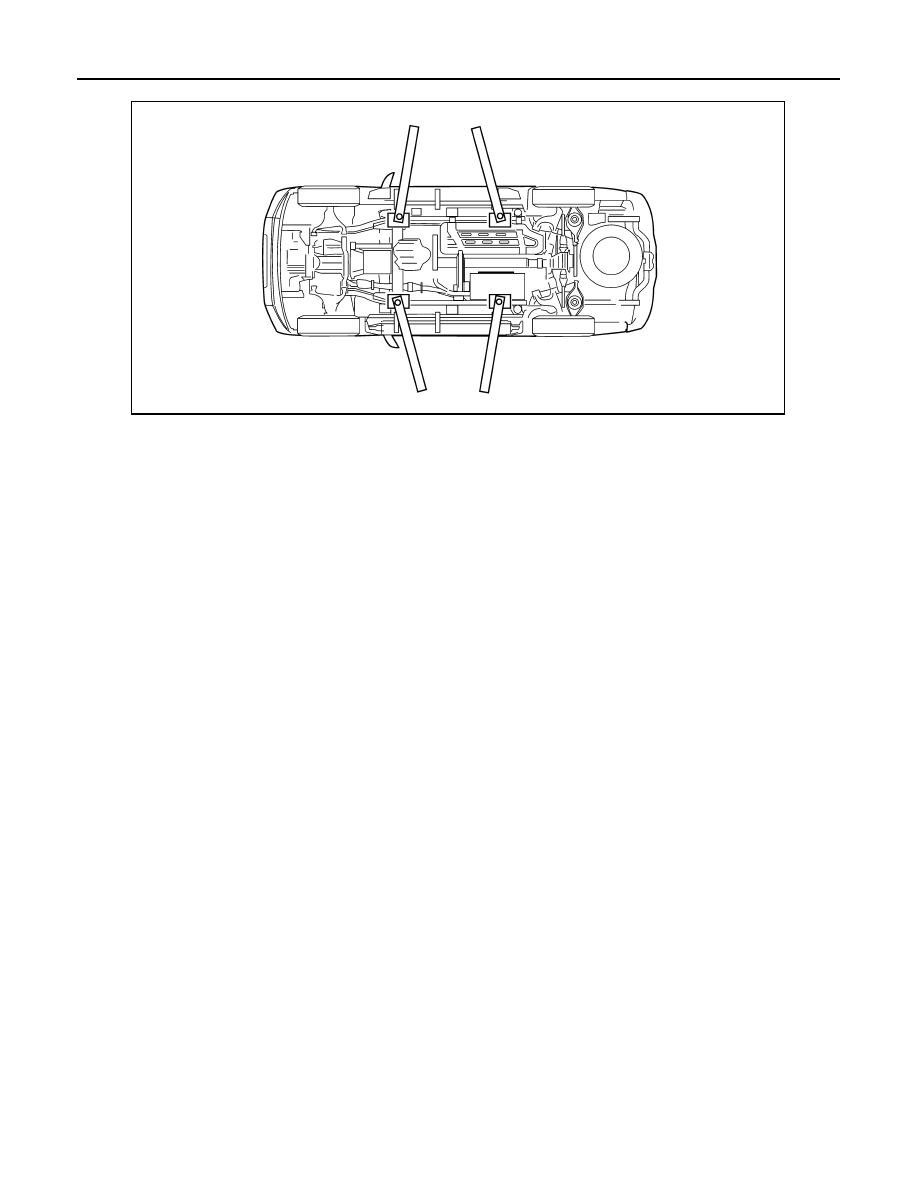
LIFTING POINT
• When setting the lift arm, do not allow the arm to contact the brake tubes, brake cable, or fuel lines.
WAIA0029E
2010 Pathfinder
|
|
|
GI-30 < PRECAUTION > LIFTING POINT • When setting the lift arm, do not allow the arm to contact the brake tubes, brake cable, or fuel lines. WAIA0029E 2010 Pathfinder |