Nissan Pathfinder (2010 year). Manual - part 425


  Index      Manuals     Nissan Pathfinder (2010 year) - Service and Repair Manual


Search            copyright infringement  


Content      ..     423      424      425      426     ..


Nissan Pathfinder (2010 year). Manual - part 425


GI-6

< HOW TO USE THIS MANUAL >

HOW TO FOLLOW TROUBLE DIAGNOSES

HOW TO FOLLOW TROUBLE DIAGNOSES

Description

INFOID:0000000005255333

NOTICE:

Trouble diagnoses indicate work procedures required to diagnose problems effectively. Observe the following

instructions before diagnosing.

• Before performing trouble diagnoses, read the “Work Flow” in each section.

• After repairs, re-check that the problem has been completely eliminated.

• Refer to Component Parts and Harness Connector Location for the Systems described in each section for

identification/location of components and harness connectors.

• When checking circuit continuity, ignition switch should be OFF.

• Refer to the Circuit Diagram for quick pinpoint check.

If you need to check circuit continuity between harness connectors in more detail, such as when a sub-har-

ness is used, refer to Wiring Diagram in each individual section and Harness Layout in PG section for identi-

fication of harness connectors.

• Before checking voltage at connectors, check battery voltage.

• After accomplishing the Diagnosis Procedures and Electrical Components Inspection, make sure that all

harness connectors are reconnected as they were.

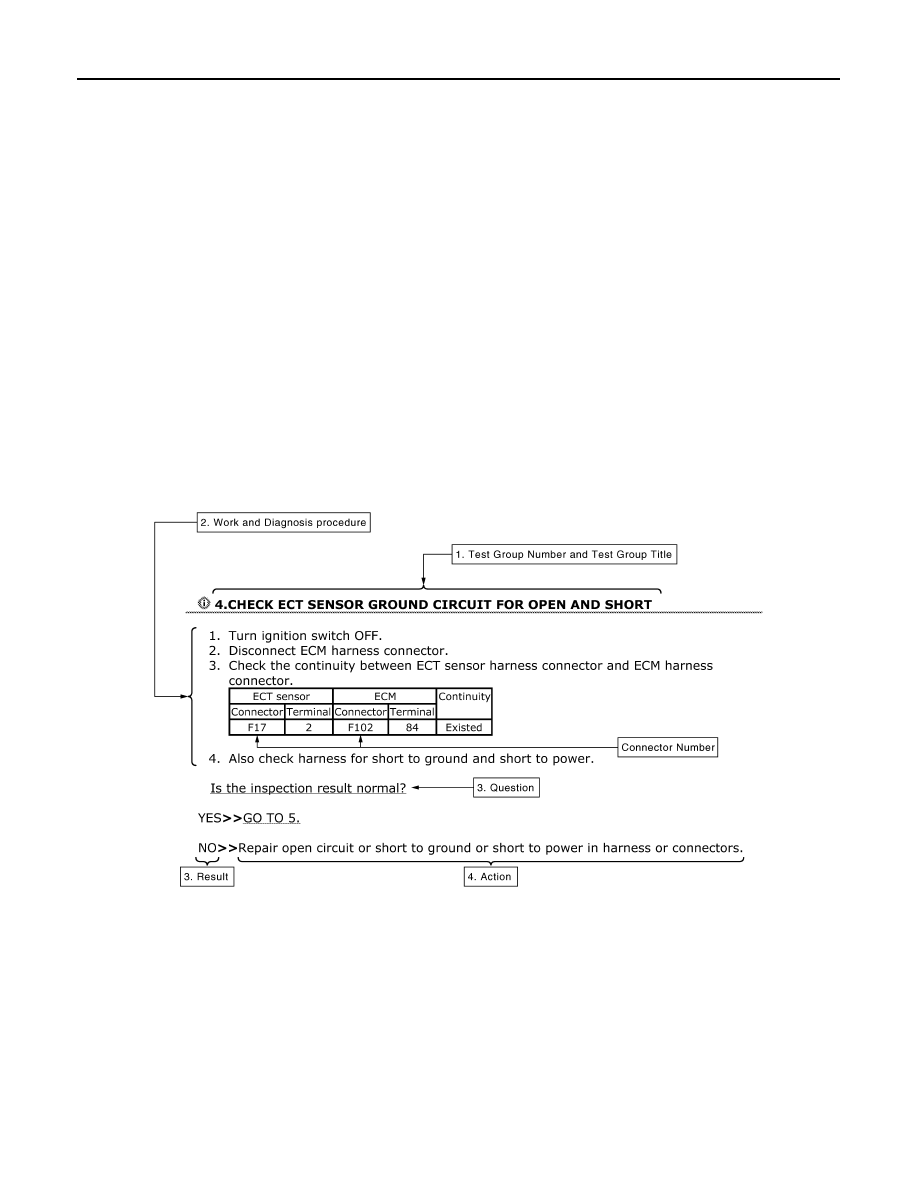
How to Follow Test Groups in Trouble Diagnosis

INFOID:0000000005255334

1. Test group number and test group title

• Test group number and test group title are shown in the upper portion of each test group.

2. Work and diagnosis procedure

• Start to diagnose a problem using procedures indicated in enclosed test groups.

3. Questions and results

• Questions and required results are indicated in test group.

4. Action

• Next action for each test group is indicated based on result of each question.

JPAIA0021GB

2010 Pathfinder

HOW TO FOLLOW TROUBLE DIAGNOSES

GI-7

< HOW TO USE THIS MANUAL >

C

D

E

F

G

H

I

J

K

L

M

B

GI

N

O

P

Key to Symbols Signifying Measurements or Procedures

INFOID:0000000005255335

SAIA1539E

2010 Pathfinder

GI-8

< HOW TO USE THIS MANUAL >

HOW TO FOLLOW TROUBLE DIAGNOSES

SAIA1540E

2010 Pathfinder

HOW TO READ WIRING DIAGRAMS

GI-9

< HOW TO USE THIS MANUAL >

C

D

E

F

G

H

I

J

K

L

M

B

GI

N

O

P

HOW TO READ WIRING DIAGRAMS

Connector symbols

INFOID:0000000005255336

Most of connector symbols in wiring diagrams are shown from the terminal side.

• Connector symbols shown from the terminal side are enclosed by

a single line and followed by the direction mark.

• Connector symbols shown from the harness side are enclosed by

a double line and followed by the direction mark.

• Certain systems and components, especially those related to

OBD, may use a new style slide-locking type harness connector.

For description and how to disconnect, refer to PG section,

“Description”, “HARNESS CONNECTOR”.

• Male and female terminals

Connector guides for male terminals are shown in black and

female terminals in white in wiring diagrams.

SAIA0257E

SGI363

2010 Pathfinder

GI-10

< HOW TO USE THIS MANUAL >

HOW TO READ WIRING DIAGRAMS

Sample/wiring diagram -example-

INFOID:0000000005255337

• For detail, refer to following 

GI-11, "Description"

.

JCAWA0005GB

2010 Pathfinder

HOW TO READ WIRING DIAGRAMS

GI-11

< HOW TO USE THIS MANUAL >

C

D

E

F

G

H

I

J

K

L

M

B

GI

N

O

P

Description

INFOID:0000000005255338

SWITCH POSITIONS 

Switches are shown in wiring diagrams as if the vehicle is in the “normal” condition.

A vehicle is in the “normal” condition when:

Number

Item

Description

1

Power supply

• This means the power supply of fusible link or fuse.

2

Fusible link

• “X” means the fusible link.

3

Number of fusible link/
fuse

• This means the number of fusible link or fuse location.

4

Fuse

• “/” means the fuse.

5

Current rating of fus-
ible link/fuse

• This means the current rating of the fusible link or fuse.

6

Optional splice

• The open circle shows that the splice is optional depending on vehicle application.

7

Connector number

• The letter shows which harness the connector is located in.
• Example “M”: main harness. For detail and to locate the connector, refer to 

PG-65, "Elec-

trical Units Location"

PG-39, "Harness Layout"

.

8

Splice

• The shaded circle “

” means the splice.

9

Page crossing

• This circuit continues to an adjacent page.

10

Option abbreviation

• This means the vehicle specifications which layouts the circuit between “ ”.

11

Relay

• This shows an internal representation of the relay.

12

Option description

• This shows a description of the option abbreviation used on the page.

13

Switch

• This shows that continuity exists between terminals 1 and 2 when the switch is in the A 

position. Continuity exists between terminals 1 and 3 when the switch is in the B position.

14

Circuit (Wiring)

• This means the wiring.

15

System branch

• This shows that the circuit is branched to other systems.

16

Shielded line

• The line enclosed by broken line circle shows shield wire.

17

Component name

• This shows the name of a component.

18

Ground (GND)

• This shows the ground connection.

19

Connector

• This means the connector information.
• This unit-side is described by the connector symbols.

20

Connectors

• This means that a transmission line bypasses two connectors or more.

21

Wire color

• This shows a code for the color of the wire.

B = Black
W = White
R = Red
G = Green
L = Blue
Y = Yellow
LG = Light Green

BR = Brown
OR or O = Orange
P = Pink
PU or V (Violet) = Purple
GY or GR = Gray
SB = Sky Blue
CH = Dark Brown
DG = Dark Green

• When the wire color is striped, the base color is given first, followed by the stripe color as 

shown below:
Example: L/W = Blue with White Stripe

22

Terminal number

• This means the terminal number of a connector.

2010 Pathfinder

GI-12

< HOW TO USE THIS MANUAL >

HOW TO READ WIRING DIAGRAMS

• ignition switch is “OFF”,

• doors, hood and trunk lid/back door are closed,

• pedals are not depressed, and

• parking brake is released.

MULTIPLE SWITCH

The continuity of multiple switch is described in two ways as shown below.

• The switch chart is used in schematic diagrams.

• The switch diagram is used in wiring diagrams.

SGI860

JSAIA0017GB

2010 Pathfinder

ABBREVIATIONS

GI-13

< HOW TO USE THIS MANUAL >

C

D

E

F

G

H

I

J

K

L

M

B

GI

N

O

P

ABBREVIATIONS

Abbreviation List

INFOID:0000000005255339

The following 

ABBREVIATIONS

 are used:

ABBREVIATION

DESCRIPTION

A/C

Air Conditioner

A/T

Automatic Transaxle/Transmission

ATF

Automatic Transmission Fluid

AWD

All wheel drive

D

1

Drive range (1gr)

D

2

Drive range (2 gr)

D

3

Drive range (3 gr)

D

4

Drive range (4 gr)

FR, RR

Front, Rear

LH, RH

Left-Hand, Right-Hand

OD

Overdrive

P/S

Power Steering

SAE

Society of Automotive Engineers, Inc.

SDS

Service Data and Specifications

SST

Special Service Tools

2WD

2-Wheel Drive

4WD

4-Wheel Drive

1GR

First Gear

2GR

Second Gear

3GR

Third Gear

4GR

Fourth Gear

5GR

Fifth Gear

2

2

2nd range (2 gr)

2

1

2nd range (1gr)

1

2

1st range (2 gr)

1

1

1st range (1gr)

2010 Pathfinder


Content      ..     423      424      425      426     ..