Nissan Pathfinder (2010 year). Manual - part 410
EXL-146
< ON-VEHICLE REPAIR >
ADJUSTMENT AND INSPECTION
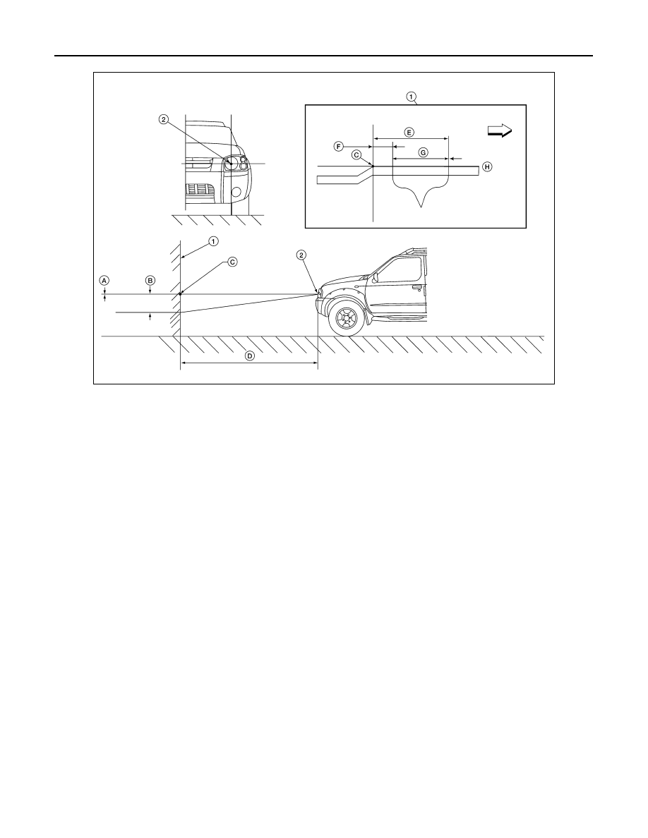
Aiming Chart
NOTE:
• By regulation, no means for horizontal aim adjustment is provided from the factory; only vertical aim is
adjustable.
• Basic illuminating area for evaluation and/or adjustment should be within range shown on aiming chart.
1. Use adjustment screw to perform aiming adjustment.
•
Cover the opposite lamp and ensure fog lamps, if equipped, are turned off.
CAUTION:
Do not tighten adjustment screw beyond specified torque or damage may occur.
2. Adjust beam pattern until cut-off line (top edge of illumination area) is positioned at the specified height off
ground. Measure cut-off line within distance J on H-line. See aiming chart.
FRONT FOG LAMP
FRONT FOG LAMP : Aiming Adjustment
INFOID:0000000005259792
The fog lamp is a semi-sealed beam type which uses a replaceable halogen bulb. Before performing aiming
adjustment, make sure of the following.
• Keep all tires inflated to correct pressure.
WKIA4885E
1
Adjustment screen
2
Headlamp bulb center (HV point)
A
Minimum acceptable vertical aim di-
mension (see aiming chart)
B
Maximum acceptable vertical aim
dimension (see aiming chart)
C
H-V point
D
Distance of headlamp aiming screen
from vehicle 7.62 m (25 ft.)
E
Maximum aim evaluation distance
from vertical center on aiming
screen 399mm (3
°
R).
F
Minimum aim evaluation distance
from vertical center on aiming
screen 133 mm (1
°
R)
G
Aim evaluation area
H
Horizontal aiming evaluation line.
⇒
Right
A (Minimum acceptable vertical aim dimension)
-3.3 mm (0.13 in)
0.025
°
up
B (Maximum acceptable vertical aim dimension) 36.6 mm (1.44 in)
0.275
°
down
Adjustment torque
1.67 N.m (17 kg-cm, 14.8 in-lb)
2010 Pathfinder