Nissan Pathfinder (2010 year). Manual - part 369


  Index      Manuals     Nissan Pathfinder (2010 year) - Service and Repair Manual


Search            copyright infringement  


Content      ..     367      368      369      370     ..


Nissan Pathfinder (2010 year). Manual - part 369


EM-80

< ON-VEHICLE REPAIR >

[VQ40DE]

CAMSHAFT

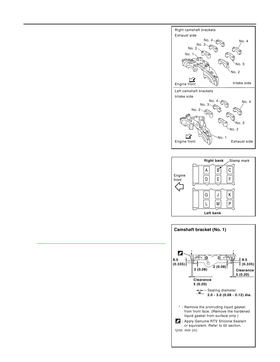
4. Install camshaft brackets.

• Remove foreign material completely from camshaft bracket

backside and from cylinder head installation face.

• Install camshaft bracket in original position and direction as

shown.

• Install camshaft brackets (No. 2 to 4) aligning the stamp marks

as shown.

NOTE:

There are no identification marks indicating left and right for

camshaft bracket (No. 1).

• Apply liquid gasket to mating surface of camshaft bracket (No.

1) as shown on right and left banks.

Use Genuine RTV Silicone Sealant or equivalent. Refer to

GI-14, "Recommended Chemical Products and Sealants"

.

PBIC2051E

PBIC2052E

PBIC2660E

2010 Pathfinder

CAMSHAFT

EM-81

< ON-VEHICLE REPAIR >

[VQ40DE]

C

D

E

F

G

H

I

J

K

L

M

A

EM

N

P

O

5. Tighten camshaft bracket bolts in the following steps, in numeri-

cal order as shown.

6. Measure the difference in levels between front end faces of

camshaft bracket (No. 1) and cylinder head. 

• Measure two positions (both intake and exhaust side) for a

single bank.

• If the measured value is out of the standard, re-install cam-

shaft bracket (No. 1).

7. Check and adjust the valve clearance. Refer to 

EM-19, "Valve Clearance"

.

8. Installation of the remaining components is in the reverse order of removal.

INSPECTION AFTER INSTALLATION

Inspection of Camshaft Sprocket (INT) Oil Groove

WARNING:

• Check when engine is cold so as to prevent burns from any splashing engine oil.

CAUTION:

• Perform this inspection only when DTC P0011 or P0021 are detected in self-diagnostic results of

CONSULT-III and it is directed according to inspection procedure of EC section. Refer to 

EC-103,

"DTC Confirmation Procedure"

.

1. Check the engine oil level. Refer to 

LU-8, "Inspection"

.

2. Perform the following procedure so as to prevent the engine from being unintentionally started while

checking.

a. Release fuel pressure. Refer to 

EC-495, "Fuel Pressure Check"

.

b. Disconnect ignition coil and injector harness connectors.
3. Remove intake valve timing control solenoid valve. Refer to 

EM-51, "Removal and Installation"

.

Camshaft bracket bolts
Step 1 (bolts 7 - 10)

: 1.96 N·m (0.2 kg-m, 17 in-lb)

Step 2 (bolts 1 - 6)

: 1.96 N·m (0.2 kg-m, 17 in-lb)

Step 3

: 5.88 N·m (0.6 kg-m, 52 in-lb)

Step 4

: 10.4 N·m (1.1 kg-m, 92 in-lb)

PBIC2050E

Standard : –0.14 to 0.14 mm (–0.0055 to 0.0055 in) 

EMQ0044D

2010 Pathfinder

EM-82

< ON-VEHICLE REPAIR >

[VQ40DE]

CAMSHAFT

4. Crank the engine, and then make sure that engine oil comes out

from camshaft bracket (No. 1) oil hole. End cranking after check-

ing.

WARNING:

• Be careful not to touch rotating parts (drive belts, idler

pulley, and crankshaft pulley, etc.).

CAUTION:

• Engine oil may squirt from intake valve timing control

solenoid valve installation hole during cranking. Use a

shop cloth to prevent the engine components and the

vehicle.

• Do not allow engine oil to get on rubber components such

as drive belt or engine mount insulators. Immediately wipe off any splashed engine oil.

• Clean oil groove between oil strainer and intake valve timing control solenoid valve if engine oil does not

come out from camshaft bracket (No. 1) oil hole. Refer to 

LU-7, "Lubrication Circuit"

LU-7, "System Chart"

.

5. Remove components between intake valve timing control solenoid valve and camshaft sprocket (INT),

and then check each oil groove for clogging.

• Clean oil groove if necessary. Refer to 

LU-7, "Lubrication Circuit"

LU-7, "System Chart"

.

6. After inspection, installation of the remaining components is in the reverse order of removal.

Inspection for Leaks

• Before starting the engine, check oil/fluid levels including engine coolant and engine oil. If the levels are

lower than required quantity, fill to the specified level. Refer to 

MA-16, "For North America"

.

• Use procedure below to check for fuel leakage.

• Turn ignition switch ON (with engine stopped). With fuel pressure applied to the fuel piping, check for fuel

leakage at the connection points.

• Start engine. With engine speed increased, check again for fuel leakage at connection points.

• Run engine to check for unusual noise and vibration.

NOTE:

If hydraulic pressure inside timing chain tensioner drops after removal and installation, slack in the guide

may generate a pounding noise during and just after engine start. However, this is normal. Noise will stop

after hydraulic pressure rises.

• Warm up engine thoroughly to make sure there is no leakage of fuel, exhaust gas, or any oil/fluids including

engine oil and engine coolant.

• Bleed air from passages in lines and hoses, such as in cooling system.

• After cooling down the engine, again check oil/fluid levels including engine oil and engine coolant. Refill to

specified level if necessary.

• Summary of the inspection items:

* Transmission/transaxle/CVT fluid, power steering fluid, brake fluid, etc.

PBIC2869E

Item

Before starting engine

Engine running

After engine stopped

Engine coolant

Level

Leakage

Level

Engine oil

Level

Leakage

Level

Other oils and fluids*

Level

Leakage

Level

Fuel

Leakage

Leakage

Leakage

Exhaust gas

Leakage

2010 Pathfinder

OIL SEAL

EM-83

< ON-VEHICLE REPAIR >

[VQ40DE]

C

D

E

F

G

H

I

J

K

L

M

A

EM

N

P

O

OIL SEAL

Removal and Installation of Valve Oil Seal

INFOID:0000000005260465

REMOVAL

1. Turn crankshaft until the cylinder requiring new oil seals is at TDC. This will prevent valve from dropping

into cylinder.

2. Remove camshaft relating to valve oil seal to be removed. Refer to 

EM-74, "Removal and Installation"

.

3. Remove valve lifters. Refer to 

EM-74, "Removal and Installation"

.

4. Remove valve collet, valve spring retainer and valve spring

using Tool.

CAUTION:

When working, take care not to damage valve lifter holes.

• Compress valve spring using Tool attachment, adapter.

Remove valve collet with magnet hand.

5. Remove valve oil seal using Tool.

INSTALLATION

1. Apply new engine oil to new valve oil seal joint surface and seal lip.
2. Press in valve oil seal to specified height "H" using Tool.

NOTE:

Dimension "H": height measured before valve spring seat instal-

lation.

3. Installation of the remaining components is in the reverse order

of removal.

Removal and Installation of Front Oil Seal

INFOID:0000000005260466

REMOVAL

1. Remove engine under cover. Refer to 

EXT-14, "Removal and Installation"

.

2. Remove drive belt. Refer to 

EM-14, "Removal and Installation"

.

3. Remove engine cooling fan assembly. Refer to 

CO-19, "Removal and Installation (Crankshaft driven

type)"

.

4. Remove crankshaft pulley. Refer to 

EM-60, "Removal and Installation"

.

Tool numbers

: KV10116200 (J-26336-B)
: KV10115900 (J-26336-20)
: KV10109220 ( — )

WBIA0578E

Tool number

: KV10107902 (J-38959)

WBIA0489E

Tool number

(J-39386)

Intake and exhaust

: 14.3 - 14.9 mm (0.563 - 0.587 in)

WBIA0490E

2010 Pathfinder

EM-84

< ON-VEHICLE REPAIR >

[VQ40DE]

OIL SEAL

5. Remove front oil seal using suitable tool.

CAUTION:

Be careful not to damage front timing chain case and crank-

shaft.

INSTALLATION

1. Apply new engine oil to both oil seal lip and dust seal lip of new front oil seal.
2. Install front oil seal.

• Install front oil seal so that each seal lip is oriented as shown.

• Press-fit until the height of front oil seal is level with the mount-

ing surface using suitable tool.

- Suitable drift: outer diameter 60 mm (2.36 in), inner diameter

50 mm (1.97 in).

CAUTION:

• Be careful not to damage front timing chain case and

crankshaft.

• Press-fit straight and avoid causing burrs or tilting oil

seal.

3. Installation is in the reverse order of removal after this step.

Removal and Installation of Rear Oil Seal

INFOID:0000000005260467

REMOVAL

1. Remove transmission assembly. Refer to 

TM-191, "2WD : Removal and Installation"

 (2WD models), 

TM-

195, "4WD : Removal and Installation"

 (4WD models).

2. Remove driveplate. Refer to 

EM-101, "Exploded View"

.

3. Remove rear oil seal with a suitable tool.

CAUTION:

Be careful not to damage crankshaft and cylinder block.

PBIC2931E

SEM715A

PBIC2931E

PBIC2932E

2010 Pathfinder

OIL SEAL

EM-85

< ON-VEHICLE REPAIR >

[VQ40DE]

C

D

E

F

G

H

I

J

K

L

M

A

EM

N

P

O

INSTALLATION

1. Apply new engine oil to new rear oil seal joint surface and seal lip.
2. Install rear oil seal so that each seal lip is oriented as shown.

• Install new rear oil seal using Tool.

CAUTION:

• Be careful not to damage crankshaft and cylinder block.

• Press-fit oil seal straight to avoid causing burrs or tilt-

ing.

• Do not touch grease applied onto oil seal lip.

• Press in rear oil seal to the position as shown.

3. Installation of the remaining components is in the reverse order of removal.

CAUTION:

• When replacing an engine or transmission you must make sure the dowels are installed cor-

rectly during reassembly.

• Improper alignment caused by missing dowels may cause vibration, oil leaks or breakage of

drivetrain components.

SEM715A

Tool number

:    —   (J-49815)
:    —   (J-8092)

PBIC2933E

SBIA0281E

2010 Pathfinder

EM-86

< ON-VEHICLE REPAIR >

[VQ40DE]

CYLINDER HEAD

CYLINDER HEAD

Exploded View

INFOID:0000000005260468

Removal and Installation

INFOID:0000000005260469

REMOVAL

1. Remove camshaft. Refer to 

EM-74, "Removal and Installation"

.

2. Remove intake manifold. Refer to 

EM-30, "Removal and Installation"

.

3. Remove exhaust manifold. Refer to 

EM-33, "Removal and Installation (Exhaust Manifold)"

.

4. Remove water inlet and thermostat assembly. Refer to 

CO-27, "Removal and Installation"

.

5. Remove water outlet, water pipe and heater pipe. Refer to 

CO-29, "Removal and Installation"

.

1.

Rubber plug

2.

Cylinder head (left bank)

3.

Cylinder head bolt

4.

Cylinder head (right bank)

5.

Harness bracket

6.

Cylinder head gasket (right bank)

7.

Cylinder head gasket (left bank)

PBIC2934E

2010 Pathfinder

CYLINDER HEAD

EM-87

< ON-VEHICLE REPAIR >

[VQ40DE]

C

D

E

F

G

H

I

J

K

L

M

A

EM

N

P

O

6. Remove cylinder head bolts in reverse order as shown using

suitable tool and power tool to remove cylinder heads (right and

left banks).

7. Remove cylinder head gaskets.

INSPECTION AFTER REMOVAL

Cylinder Head Bolts Outer Diameter

• Cylinder head bolts are tightened by plastic zone tightening

method. Whenever the size difference between “d1” and “d2”

exceeds the limit, replace the bolt with a new one. 

• If reduction of outer diameter appears in a position other than “d2”,

use it as “d2” point.

Cylinder Head Distortion

NOTE:

When performing this inspection, cylinder block distortion should be also checked. Refer to 

EM-112, "Inspec-

tion After Disassembly"

.

1. Using suitable tool, wipe off oil, scale, gasket, sealant and carbon deposits from surface of cylinder head.

CAUTION:

Do not allow gasket fragments to enter engine oil or engine coolant passages.

2. At each of several locations on bottom surface of cylinder head,

measure the distortion in six directions.

• If it exceeds the limit, replace cylinder head.

INSTALLATION

PBIC2057E

Limit (“d1” – “d2”)

: 0.11 mm (0.0043 in)

PBIC2480E

Limit

: 0.1 mm (0.004 in)

SEM861E

2010 Pathfinder


Content      ..     367      368      369      370     ..