Nissan Pathfinder (2010 year). Manual - part 368


  Index      Manuals     Nissan Pathfinder (2010 year) - Service and Repair Manual


Search            copyright infringement  


Content      ..     366      367      368      369     ..


Nissan Pathfinder (2010 year). Manual - part 368


EM-72

< ON-VEHICLE REPAIR >

[VQ40DE]

REAR TIMING CHAIN CASE

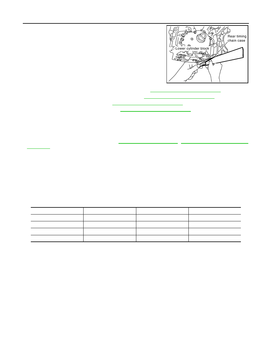
g. After installing rear timing chain case, check the surface height

difference between following parts on oil pan (upper) mounting

surface.

• If not within the standard, repeat the installation procedure.

2. Install water pump with new O-rings, if removed. Refer to 

CO-22, "Removal and Installation"

.

3. Install timing chains and related components. Refer to 

EM-60, "Removal and Installation"

.

4. Install front timing chain case. Refer to 

EM-51, "Removal and Installation"

.

5. Install oil pan (upper) and (lower). Refer to 

EM-36, "Removal and Installation"

.

INSPECTION AFTER INSTALLATION

Inspection for Leaks

The following are procedures for checking fluid leaks, lubricant leaks and exhaust gases leaks.

• Before starting engine, check oil/fluid levels including engine coolant and engine oil. If less than required

quantity, fill to the specified level. Refer to 

MA-16, "For North America"

MA-17, "For Mexico: Fluids and

Lubricants"

.

• Run engine to check for unusual noise and vibration.

NOTE:

If hydraulic pressure inside timing chain tensioner drops after removal/installation, slack in the guide may

generate a pounding noise during and just after engine start. However, this is normal. Noise will stop after

hydraulic pressure rises.

• Warm up engine thoroughly to make sure there is no leakage of fuel, exhaust gases, or any oil/fluids includ-

ing engine oil and engine coolant.

• Bleed air from lines and hoses of applicable lines, such as in cooling system.

• After cooling down engine, again check oil/fluid levels including engine oil and engine coolant. Refill to the

specified level, if necessary.

Summary of the inspection items:

* Transmission fluid, power steering fluid, brake fluid, etc.

Standard

Rear timing chain case to lower cylinder block:

–0.24 to 0.14 mm (–0.0094 to 0.0055 in)

PBIC2925E

Item

Before starting engine

Engine running

After engine stopped

Engine coolant

Level

Leakage

Level

Engine oil

Level

Leakage

Level

Other oils and fluid*

Level

Leakage

Level

Fuel

Leakage

Leakage

Leakage

2010 Pathfinder

CAMSHAFT

EM-73

< ON-VEHICLE REPAIR >

[VQ40DE]

C

D

E

F

G

H

I

J

K

L

M

A

EM

N

P

O

CAMSHAFT

Exploded View

INFOID:0000000005260463

1.

Intake valve timing control solenoid 
valve (RH bank)

2.

Gasket

3.

Camshaft bracket (No. 2 to 4)

4.

Camshaft (EXH)

5.

Camshaft (INT)

6.

Camshaft bracket (No. 1)

7.

Dowel pin

8.

Valve lifter

9.

O-ring

10.

Timing chain tensioner (secondary) 
(RH bank)

11. Spring

12. Plunger

13.

Timing chain tensioner (secondary) 
(LH bank)

14. Cylinder head (RH bank)

15. Cylinder head (LH bank)

16. O-ring

17.

Camshaft position sensor (PHASE) 
(RH bank)

18.

Camshaft position sensor (PHASE) 
(LH bank)

19. Intake valve timing control solenoid 

valve (LH bank)

PBIC2930E

2010 Pathfinder

EM-74

< ON-VEHICLE REPAIR >

[VQ40DE]

CAMSHAFT

Removal and Installation

INFOID:0000000005260464

REMOVAL

1. Release the fuel pressure (LH only). Refer to 

EC-495, "Fuel Pressure Check"

.

2. Disconnect the battery negative terminal. Refer to 

PG-78, "Removal and Installation"

.

3. Remove front wheels and tires. Refer to 

WT-49, "Rotation"

.

4. Remove front fender protectors. Refer to 

EXT-23, "Removal and Installation of Front Fender Protector"

.

5. Remove front timing chain case, camshaft sprockets, timing chains and rear timing chain case. Refer to

EM-68, "Removal and Installation"

.

6. Remove camshaft position sensor (PHASE) (right and left

banks) from cylinder head back side.

CAUTION:

• Handle carefully to avoid dropping and shocks.

• Do not disassemble.

• Do not allow metal powder to adhere to magnetic part at

sensor tip.

• Do not place sensors in a location where they are

exposed to magnetism.

7. Remove intake valve timing control solenoid valves.

• Discard intake valve timing control solenoid valve gaskets and

use new gaskets for installation.

8. Remove camshaft brackets.

• Mark camshafts, camshaft brackets and bolts so they are placed in the same position and direction for

installation.

KBIA1046E

WBIA0169E

2010 Pathfinder

CAMSHAFT

EM-75

< ON-VEHICLE REPAIR >

[VQ40DE]

C

D

E

F

G

H

I

J

K

L

M

A

EM

N

P

O

• Equally loosen camshaft bracket bolts in several steps in

reverse order as shown.

9. Remove camshafts.
10. Remove valve lifters, if necessary.

• Identify installation positions, and store them without mixing them up.

11. Remove timing chain tensioner (secondary) from cylinder head.

• Remove timing chain tensioner (secondary) with its stopper

pin attached.

NOTE:

Stopper pin was attached when timing chain (secondary) was

removed.

INSPECTION AFTER REMOVAL

Camshaft Runout

1. Put V-block on precise flat table, and support No. 2 and 4 journal

of camshaft.

CAUTION:

Do not support journal No. 1 (on the side of camshaft

sprocket) because it has a different diameter from the other

three locations.

2. Set dial indicator vertically to No. 3 journal.
3. Turn camshaft to one direction with hands, and measure the

camshaft runout on dial indicator. (Total indicator reading)

4. If it exceeds the limit, replace camshaft.

Camshaft Cam Height

PBIC2050E

PBIC2111E

Standard

: Less than 0.02 mm (0.0008 in)

Limit

: 0.05 mm (0.0020 in)

PBIC0929E

2010 Pathfinder

EM-76

< ON-VEHICLE REPAIR >

[VQ40DE]

CAMSHAFT

1. Measure the camshaft cam height with micrometer.

2. If wear exceeds the limit, replace camshaft.

Camshaft Journal Oil Clearance

CAMSHAFT JOURNAL DIAMETER

• Measure the outer diameter of camshaft journal with micrometer.

CAMSHAFT BRACKET INNER DIAMETER


• Tighten camshaft bracket bolt with the specified torque. 

• Measure the inner diameter “A” of camshaft bracket with bore

gauge.

CAMSHAFT JOURNAL OIL CLEARANCE

• (Oil clearance) = (Camshaft bracket inner diameter) – (Camshaft journal diameter).

• If the calculated value exceeds the limit, replace either or both camshaft and cylinder head.

NOTE:

Camshaft bracket cannot be replaced as a single part, because it is machined together with cylinder head.

Replace whole cylinder head assembly.

Camshaft End Play

Standard:

Intake

: 45.465 - 45.655 mm (1.7900 - 1.7974 in)

Exhaust : 45.075 - 45.265 mm (1.7746 - 1.7821 in)

Limit:

Intake

: 45.265 mm (1.7821 in)

Exhaust : 44.875 mm (1.7667 in)

EMQ0072D

Standard:

No. 1

: 25.935 - 25.955 mm (1.0211 - 1.0218 in)

No. 2, 3, 4

: 23.445 - 23.465 mm (0.9230 - 0.9238 in)

PBIC0040E

Standard:

No. 1

: 26.000 - 26.021 mm (1.0236 - 1.0244 in)

No. 2, 3, 4

: 23.500 - 23.521 mm (0.9252 - 0.9260 in)

PBIC1645E

Standard:

No. 1

: 0.045 - 0.086 mm (0.0018 - 0.0034 in)

No. 2, 3, 4 : 0.035 - 0.076 mm (0.0014 - 0.0030 in)

Limit

: 0.15 mm (0.0059 in)

2010 Pathfinder

CAMSHAFT

EM-77

< ON-VEHICLE REPAIR >

[VQ40DE]

C

D

E

F

G

H

I

J

K

L

M

A

EM

N

P

O

• Install dial indicator in thrust direction on front end of camshaft.

Measure the end play of dial indicator when camshaft is moved for-

ward/backward (in direction to axis).

• Measure the following parts if out of the limit.

- Dimension “A” for camshaft No. 1 journal

- Dimension “B” for cylinder head No. 1 journal bearing

• Following the standards above, replace camshaft and/or cylinder

head.

Camshaft Sprocket Runout

1. Put V-block on precise flat table, and support No. 2 and 4 journal of camshaft.

CAUTION:

Do not support journal No. 1 (on the side of camshaft sprocket) because it has a different diameter

from the other three locations.

2. Measure the camshaft sprocket runout with dial indicator. (Total

indicator reading)

• If it exceeds the limit, replace camshaft sprocket.

Valve Lifter 

Check if surface of valve lifter has any wear or cracks.

• If anything above is found, replace valve lifter. Refer to 

EM-128,

"Standard and Limit"

.

Valve Lifter Clearance

VALVE LIFTER OUTER DIAMETER

Standard

: 0.115 - 0.188 mm (0.0045 - 0.0074 in)

Limit

: 0.24 mm (0.0094 in)

SEM864E

Standard

: 27.500 - 27.548 mm (1.0827 - 1.0846 in)

Standard

: 27.360 - 27.385 mm (1.0772 - 1.0781 in)

KBIA2404J

Limit

: 0.15 mm (0.0059 in)

PBIC0930E

KBIA0182E

2010 Pathfinder

EM-78

< ON-VEHICLE REPAIR >

[VQ40DE]

CAMSHAFT

• Measure the outer diameter at 1/2 height of valve lifter with

micrometer since valve lifter is in barrel shape.

VALVE LIFTER HOLE DIAMETER

• Measure the inner diameter of valve lifter hole of cylinder head with

inside micrometer.

VALVE LIFTER CLEARANCE

• (Valve lifter clearance) = (Valve lifter hole diameter) – (Valve lifter outer diameter), Refer to 

EM-19, "Valve

Clearance"

.

• If the calculated value is out of the standard, referring to each standard of valve lifter outer diameter and

valve lifter hole diameter, replace either or both valve lifter and cylinder head.

INSTALLATION

1. Install timing chain tensioners (secondary) on both sides of cyl-

inder head.

• Install timing chain tensioner with its stopper pin attached. 

• Install timing chain tensioner with sliding part facing downward

on right-side cylinder head, and with sliding part facing upward

on left-side cylinder head.

• Install new O-rings as shown.

2. Install valve lifters.

• Install it in the original position.

3. Install camshafts.

Standard (Intake and exhaust)

: 33.977 - 33.987 mm (1.3377 - 1.3381 in)

JEM798G

Standard (Intake and exhaust)

: 34.000 - 34.016 mm (1.3386 - 1.3392 in)

SEM867E

Standard (Intake and exhaust)

: 0.013 - 0.039 mm (0.0005 - 0.0015 in)

PBIC2111E

2010 Pathfinder

CAMSHAFT

EM-79

< ON-VEHICLE REPAIR >

[VQ40DE]

C

D

E

F

G

H

I

J

K

L

M

A

EM

N

P

O

• Install camshaft with dowel pin attached to its front end face on

the exhaust side.

• Follow your identification marks made during removal, or fol-

low the identification marks that are present on new camshafts

for proper placement and direction.

• Install camshaft so that dowel pin hole and dowel pin on front

end face are positioned as shown. (No. 1 cylinder TDC on its

compression stroke)

NOTE:

• Large and small pin holes are located on front end face of

camshaft (INT), at intervals of 180

°

. Face small dia. side pin

hole upward (in cylinder head upper face direction).

• Though camshaft does not stop at the portion as shown, for

the placement of cam nose, it is generally accepted cam-

shaft is placed for the same direction as shown.

KBIA1071E

Bank

INT/EXH

Dowel pin

Paint marks

Identification 

mark

M1

M2

RH

INT

No

Green

No

RE

EXH

Yes

No

White

RE

LH

INT

No

Green

No

LH

EXH

Yes

No

White

LH

KBIA1009E

PBIC2478E

2010 Pathfinder


Content      ..     366      367      368      369     ..