Nissan Pathfinder (2010 year). Manual - part 326


  Index      Manuals     Nissan Pathfinder (2010 year) - Service and Repair Manual


Search            copyright infringement  


Content      ..     324      325      326      327     ..


Nissan Pathfinder (2010 year). Manual - part 326


EC-700

< COMPONENT DIAGNOSIS >

[VK56DE]

P0340 CMP SENSOR (PHASE)

P0340 CMP SENSOR (PHASE)

Component Description

INFOID:0000000005257663

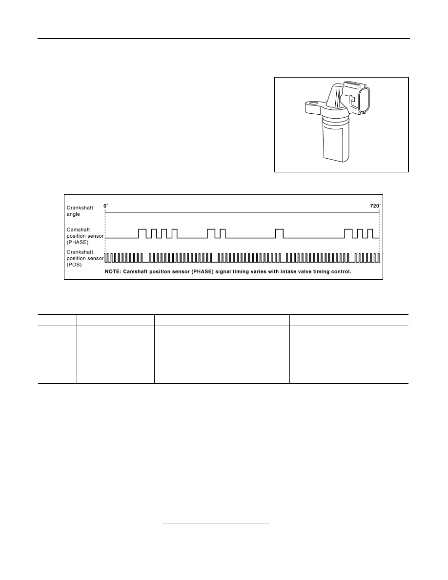
The camshaft position sensor (PHASE) senses the protrusion of

exhaust valve cam sprocket to identify a particular cylinder. The

camshaft position sensor (PHASE) senses the piston position.

When the crankshaft position sensor (POS) system becomes inoper-

ative, the camshaft position sensor (PHASE) provides various con-

trols of engine parts instead, utilizing timing of cylinder identification

signals.

The sensor consists of a permanent magnet and Hall IC.

When engine is running, the high and low parts of the teeth cause

the gap with the sensor to change.

The changing gap causes the magnetic field near the sensor to

change.

Due to the changing magnetic field, the voltage from the sensor changes. 

ECM receives the signals as shown in the figure.

On Board Diagnosis Logic

INFOID:0000000005257664

DTC Confirmation Procedure

INFOID:0000000005257665

NOTE:

If DTC Confirmation Procedure has been previously conducted, always perform the following procedure

before conducting the next step.

1. Turn ignition switch OFF and wait at least 10 seconds.

2. Turn ignition switch ON.

3. Turn ignition switch OFF and wait at least 10 seconds.

TESTING CONDITION:

Before performing the following procedure, confirm that battery voltage is more than 10.5 V with igni-

tion switch ON.

1. Turn ignition switch ON.
2. Crank engine for at least 2 seconds and run it for at least 5 seconds at idle speed.
3. Check 1st trip DTC.
4. If 1st trip DTC is detected, go to 

EC-701, "Diagnosis Procedure"

.

If 1st trip DTC is not detected, go to next step.

5. Maintaining engine speed at more than 800 rpm for at least 5 seconds.
6. Check 1st trip DTC.

PBIB0562E

JMBIA1046GB

DTC No.

Trouble diagnosis name

DTC detecting condition

Possible cause

P0340
0340

Camshaft position sensor 
(PHASE) circuit

• The cylinder No. signal is not sent to ECM for 

the first few seconds during engine cranking.

• The cylinder No. signal is not sent to ECM 

during engine running.

• The cylinder No. signal is not in the normal 

pattern during engine running.

• Harness or connectors

(The sensor circuit is open or shorted)

• Camshaft position sensor (PHASE)
• Camshaft (Exhaust)
• Starter  motor
• Starting system circuit
• Dead (Weak) battery

2010 Pathfinder

P0340 CMP SENSOR (PHASE)

EC-701

< COMPONENT DIAGNOSIS >

[VK56DE]

C

D

E

F

G

H

I

J

K

L

M

A

EC

N

P

O

7. If 1st trip DTC is detected, go to 

EC-701, "Diagnosis Procedure"

.

Diagnosis Procedure

INFOID:0000000005257666

1.

CHECK STARTING SYSTEM

Turn ignition switch to the START position.

Yes or No

Yes

>> GO TO 2.

No

>> Check starting system. (Refer to 

STR-5, "Work Flow"

.)

2.

CHECK GROUND CONNECTIONS

1. Turn ignition switch OFF.

2. Loosen and retighten ground screws on the body.

Refer to 

EC-577, "Ground Inspection"

.

OK or NG

OK

>> GO TO 3.

NG

>> Repair or replace ground connections.

3.

CHECK CAMSHAFT POSITION SENSOR (PHASE) POWER SUPPLY CIRCUIT

1. Disconnect camshaft position (CMP) sensor (PHASE) (2) har-

ness connector.

-

Radiator hose (1)

-

: Vehicle front

2. Turn ignition switch ON.

3. Check voltage between CMP sensor (PHASE) terminal 3 and

ground with CONSULT-III or tester.

OK or NG

OK

>> GO TO 5.

NG

>> GO TO 4.

4.

DETECT MALFUNCTIONING PART

Check the following.

Does the engine turn over?
Does the starter motor operate?

BBIA0539E

BBIA0740E

Voltage: Battery voltage

SEF481Y

2010 Pathfinder

EC-702

< COMPONENT DIAGNOSIS >

[VK56DE]

P0340 CMP SENSOR (PHASE)

• Harness connectors F32, E2

• IPDM E/R harness connector E119

• Harness for open or short between camshaft position sensor (PHASE) and ECM

• Harness for open or short between camshaft position sensor (PHASE) and IPDM E/R

>> Repair open circuit or short to ground or short to power in harness or connectors.

5.

CHECK CMP SENSOR (PHASE) GROUND CIRCUIT FOR OPEN AND SHORT

1. Turn ignition switch OFF.

2. Check harness continuity between CMP sensor (PHASE) terminal 1 and ground.

Refer to Wiring Diagram.

3. Also check harness for short to power.
OK or NG

OK

>> GO TO 7.

NG

>> GO TO 6.

6.

DETECT MALFUNCTIONING PART

Check the following.

• Harness connectors F32, E2

• Harness for open or short between CMP sensor (PHASE) and ground

>> Repair open circuit or short to power in harness or connectors.

7.

CHECK CMP SENSOR (PHASE) INPUT SIGNAL CIRCUIT FOR OPEN AND SHORT

1. Disconnect ECM harness connector.

2. Check harness continuity between ECM terminal 14 and CMP sensor (PHASE) terminal 2. 

Refer to Wiring Diagram.

3. Also check harness for short to ground and short to power.
OK or NG

OK

>> GO TO 8.

NG

>> Repair open circuit or short to ground or short to power in harness or connectors.

8.

CHECK CAMSHAFT POSITION SENSOR (PHASE)

Refer to 

EC-702, "Component Inspection"

.

OK or NG

OK

>> GO TO 9.

NG

>> Replace camshaft position sensor (PHASE).

9.

CHECK INTERMITTENT INCIDENT

Refer to 

GI-37, "Intermittent Incident"

.

>>

INSPECTION END

Component Inspection

INFOID:0000000005257667

CAMSHAFT POSITION SENSOR (PHASE)

1. Loosen the fixing bolt of the sensor.
2. Disconnect camshaft position sensor (PHASE) harness connector.
3. Remove the sensor.

Continuity should exist.

Continuity should exist.

2010 Pathfinder

P0340 CMP SENSOR (PHASE)

EC-703

< COMPONENT DIAGNOSIS >

[VK56DE]

C

D

E

F

G

H

I

J

K

L

M

A

EC

N

P

O

4. Visually check the sensor for chipping.

5. Check resistance as shown in the figure.

PBIB0563E

Terminal No. (Polarity)

Resistance [at 25

°

C (77

°

F)]

3(+) - 1 (-)

Except 0 or 


2 (+) - 1 (-)

3 (+) - 2 (-)

PBIB0564E

2010 Pathfinder

EC-704

< COMPONENT DIAGNOSIS >

[VK56DE]

P0420, P0430 THREE WAY CATALYST FUNCTION

P0420, P0430 THREE WAY CATALYST FUNCTION

On Board Diagnosis Logic

INFOID:0000000005257668

The ECM monitors the switching frequency ratio of air fuel sensor

(A/F) sensor 1 and heated oxygen sensor 2.

A three way catalyst (manifold) with high oxygen storage capacity

will indicate a low switching frequency of heated oxygen sensor 2.

As oxygen storage capacity decreases, the heated oxygen sensor 2

switching frequency will increase.

When the frequency ratio of air fuel ratio (A/F) sensor 1 and heated

oxygen sensor 2 approaches a specified limit value, the three way

catalyst (manifold) malfunction is diagnosed.

DTC Confirmation Procedure

INFOID:0000000005257669

NOTE:

If DTC Confirmation Procedure has been previously conducted, always perform the following procedure

before conducting the next step.

1. Turn ignition switch OFF and wait at least 10 seconds.

2. Turn ignition switch ON.

3. Turn ignition switch OFF and wait at least 10 seconds.

 WITH CONSULT-III

TESTING CONDITION:

Do not hold engine speed for more than the specified minutes below.

1. Turn ignition switch ON and select “DATA MONITOR” mode with CONSULT-III.
2. Start engine and warm it up to the normal operating temperature.
3. Turn ignition switch OFF and wait at least 10 seconds.
4. Turn ignition switch ON.
5. Turn ignition switch OFF and wait at least 10 seconds.
6. Start engine and keep the engine speed between 3,500 and 4,000 rpm for at least 1 minute under no load.
7. Let engine idle for 1 minute.
8. Check that “COOLAN TEMP/S” indicates more than 70

°

C (158

°

F).

If not, warm up engine and go to next step when “COOLAN TEMP/S” indication reaches 70

°

C (158

°

F).

9. Open engine hood.
10. Select “DTC & SRT CONFIRMATION” then “SRT WORK SUPPORT” mode with CONSULT-III.
11. Rev engine between 2,000 and 3,000 rpm and hold it for 3 consecutive minutes, then release the acceler-

ator pedal completely.

If “INCMP” of “CATALYST” changed to “CMPLT”, go to step 14.

12. Wait 5 seconds at idle.
13. Rev engine between 2,000 and 3,000 rpm and maintain it until “INCMP” of “CATALYST” changes to

“CMPLT” (It will take approximately 5 minutes).

If not “CMPLT”, stop engine and cool it down to less than 70

°

C (158

°

F), and then retest from step 1.

14. Select “SELF-DIAG RESULTS” mode with CONSULT-III.

PBIB2055E

DTC No.

Trouble diagnosis name

DTC detecting condition

Possible cause

P0420
0420
(Bank 1)

Catalyst system efficiency 
below threshold

• Three way catalyst (manifold) does not 

operate properly.

• Three way catalyst (manifold) does not 

have enough oxygen storage capacity.

• Three way catalyst (manifold)
• Exhaust tube
• Intake air leakage
• Fuel injector
• Fuel injector leakage
• Spark  plug
• Improper ignition timing

P0430
0430
(Bank 2)

2010 Pathfinder

P0420, P0430 THREE WAY CATALYST FUNCTION

EC-705

< COMPONENT DIAGNOSIS >

[VK56DE]

C

D

E

F

G

H

I

J

K

L

M

A

EC

N

P

O

15. Check 1st trip DTC.

If the 1st trip DTC is detected, go to 

EC-705, "Diagnosis Procedure"

.

Overall Function Check

INFOID:0000000005257670

Use this procedure to check the overall function of the three way catalyst (manifold). During this check, a 1st

trip DTC might not be confirmed.

 WITH GST

1. Start engine and warm it up to the normal operating temperature.
2. Turn ignition switch OFF and wait at least 10 seconds.
3. Start engine and keep the engine speed between 3,500 and 4,000 rpm for at least 1 minute under no load.
4. Let engine idle for 1 minute.
5. Open engine hood.
6. Set voltmeter probes between ECM terminal 55 [HO2S2 (bank

1) signal] and ground, ECM terminal 74 [HO2S2 (bank 2) signal]

and ground.

7. Keep engine speed at 2,500 rpm constant under no load.
8. Check that the voltage does not vary for more than 5 seconds.

If the voltage fluctuation cycle takes less than 5 seconds, go to

EC-705, "Diagnosis Procedure"

.

• 1 cycle: 0.6 - 1.0 

 0 - 0.3 

 0.6 - 1.0

Diagnosis Procedure

INFOID:0000000005257671

1.

CHECK EXHAUST SYSTEM

Visually check exhaust tubes and muffler for dents.
OK or NG

OK

>> GO TO 2.

NG

>> Repair or replace malfunctioning part.

2.

CHECK EXHAUST GAS LEAKAGE

1. Start engine and run it at idle.

2. Listen for an exhaust gas leakage before the three way catalyst (manifold).

OK or NG

OK

>> GO TO 3.

NG

>> Repair or replace malfunctioning part.

3.

CHECK INTAKE AIR LEAKAGE

Listen for an intake air leakage after the mass air flow sensor.
OK or NG

OK

>> GO TO 4.

NG

>> Repair or replace malfunctioning part.

4.

CHECK IGNITION TIMING

PBIB2056E

PBIB1216E

2010 Pathfinder

EC-706

< COMPONENT DIAGNOSIS >

[VK56DE]

P0420, P0430 THREE WAY CATALYST FUNCTION

Check the following items. Refer to 

EC-506, "Basic Inspection"

.

OK or NG

OK

>> GO TO 5.

NG

>> Follow the instructions on 

EC-506, "Basic Inspection"

.

5.

CHECK FUEL INJECTOR

1. Stop engine and then turn ignition switch ON.

2. Check voltage between ECM terminals 21, 22, 23, 40, 41, 42,

44, 63 and ground with CONSULT-III or tester.

OK or NG

OK

>> GO TO 6.

NG

>> Perform 

EC-875, "Diagnosis Procedure"

.

6.

CHECK FUNCTION OF IGNITION COIL-I

CAUTION:

Never following procedure in a place with no combustible objects and good ventilation.

1. Turn ignition switch OFF.

2. Remove fuel pump fuse (1) in IPDM E/R (2) to release fuel pres-

sure.

NOTE:

Do not use CONSULT-III to release fuel pressure, or fuel pres-

sure applies again during the following procedure.

3. Start engine.

4. After engine stalls, crank it 2 or 3 times to release all fuel pres-

sure.

5. Turn ignition switch OFF.

6. Remove all ignition coil harness connectors to avoid the electri-

cal discharge from the ignition coils.

7. Remove ignition coil and spark plug of the cylinder to be

checked.

8. Crank engine for 5 seconds or more to remove combustion gas in the cylinder.

9. Connect spark plug and harness connector to ignition coil.

10. Fix ignition coil using a rope etc. with gap of 13 - 17 mm

between the edge of the spark plug and grounded metal portion

as shown in the figure.

11. Crank engine for approximately 3 seconds, and check whether

spark is generated between the spark plug and the grounded

metal portion.

CAUTION:

• Never place the spark plug and the ignition coil within 50

cm each other. Be careful not to get an electrical shock

while checking, because the electrical discharge voltage

becomes 20 kV or more.

• It might damage the ignition coil if the gap of more than 17 mm is made.

NOTE:

When the gap is less than 13 mm, a spark might be generated even if the coil is malfunctioning.

Items

Specifications

Idle speed

650 

±

 50 rpm (in P or N position)

Ignition timing

15 

±

 5

°

BTDC (in P or N position)

Battery voltage should exist.

PBIB1527E

Spark should be generated.

ALBIA0351ZZ

PBIB2325E

2010 Pathfinder

P0420, P0430 THREE WAY CATALYST FUNCTION

EC-707

< COMPONENT DIAGNOSIS >

[VK56DE]

C

D

E

F

G

H

I

J

K

L

M

A

EC

N

P

O

OK or NG

OK

>> GO TO 10.

NG

>> GO TO 7.

7.

CHECK FUNCTION OF IGNITION COIL-II

1. Turn ignition switch OFF.

2. Disconnect spark plug and connect a non-malfunctioning spark plug.

3. Crank engine for approximately 3 seconds, and recheck whether spark is generated between the spark

plug and the grounded metal portion.

OK or NG

OK

>> GO TO 8.

NG

>> Check ignition coil, power transistor and their circuits. Refer to 

EC-881, "Diagnosis Procedure"

.

8.

CHECK SPARK PLUG

Check the initial spark plug for fouling, etc.
OK or NG

OK

>> Replace malfunctioning spark plug(s) with standard type

one(s). For spark plug type, refer to 

EM-244, "Standard

and Limit"

.

NG

>> 1. Repair or clean spark plug.

2. GO TO 9.

9.

CHECK FUNCTION OF IGNITION COIL-III

1. Reconnect the initial spark plugs.

2. Crank engine for approximately 3 seconds, and recheck whether spark is generated between the spark

plug and the grounded portion.

OK or NG

OK

>>

INSPECTION END

NG

>> Replace malfunctioning spark plug(s) with standard type one(s). For spark plug type, refer to 

EM-

244, "Standard and Limit"

.

10.

CHECK FUEL INJECTOR

1. Turn ignition switch OFF.

2. Remove fuel injector assembly. Refer to 

EM-176, "Removal and Installation"

.

Keep fuel hose and all fuel injectors connected to fuel injector gallery.

3. Disconnect all ignition coil harness connectors.

4. Reconnect all fuel injector harness connector disconnected.

5. Turn ignition switch ON.

Make sure fuel does not drip from fuel injector.

OK or NG

OK (Does not drip.)>>GO TO 11.

NG (Drips.)>>Replace the fuel injector(s) from which fuel is dripping.

11.

CHECK INTERMITTENT INCIDENT

Refer to 

GI-37, "Intermittent Incident"

.

Trouble is fixed.>>

INSPECTION END

Trouble is not fixed.>>Replace malfunctioning three way catalyst assembly.

Spark should be generated.

SEF156I

Spark should be generated.

2010 Pathfinder


Content      ..     324      325      326      327     ..