Nissan Pathfinder (2010 year). Manual - part 314


  Index      Manuals     Nissan Pathfinder (2010 year) - Service and Repair Manual


Search            copyright infringement  


Content      ..     312      313      314      315     ..


Nissan Pathfinder (2010 year). Manual - part 314


EC-604

< COMPONENT DIAGNOSIS >

[VK56DE]

P0102, P0103 MAF SENSOR

Diagnosis Procedure

INFOID:0000000005257558

1.

INSPECTION START

Which malfunction (P0102 or P0103) is duplicated?
P0102 or P0103

P0102 >> GO TO 2.

P0103 >> GO TO 3.

2.

CHECK INTAKE SYSTEM

Check the following for connection.

• Air duct

• Vacuum hoses

• Intake air passage between air duct to intake manifold
OK or NG

OK

>> GO TO 3.

NG

>> Reconnect the parts.

3.

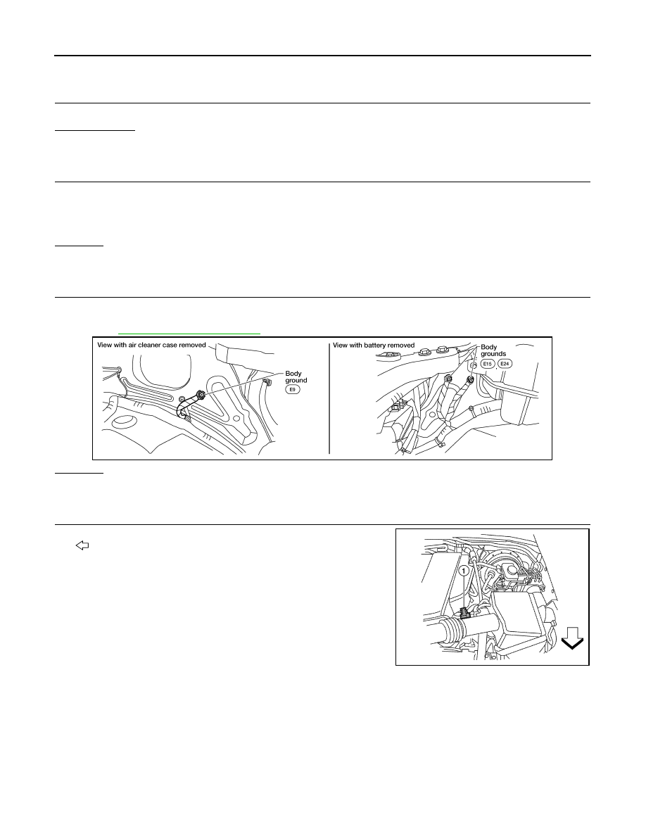
RETIGHTEN GROUND SCREWS

1. Turn ignition switch OFF.

2. Loosen and retighten ground screws on the body.

Refer to 

EC-577, "Ground Inspection"

.

OK or NG

OK

>> GO TO 4.

NG

>> Repair or replace ground connections.

4.

CHECK MASS AIR FLOW SENSOR POWER SUPPLY CIRCUIT

1. Disconnect mass air flow (MAF) sensor (1) harness connector.
-

: Vehicle front

2. Turn ignition switch ON.

BBIA0539E

ALBIA0353ZZ

2010 Pathfinder

P0102, P0103 MAF SENSOR

EC-605

< COMPONENT DIAGNOSIS >

[VK56DE]

C

D

E

F

G

H

I

J

K

L

M

A

EC

N

P

O

3. Check voltage between MAF sensor terminal 2 and ground with

CONSULT-III or tester. 

OK or NG

OK

>> GO TO 6.

NG

>> GO TO 5.

5.

DETECT MALFUNCTIONING PART

Check the following.

• Harness connectors E2, F32

• IPDM E/R harness connector E119

• Harness for open or short between mass air flow sensor and IPDM E/R

• Harness for open or short between mass air flow sensor and ECM

>> Repair harness or connectors.

6.

CHECK MAF SENSOR GROUND CIRCUIT FOR OPEN AND SHORT

1. Turn ignition switch OFF.

2. Disconnect ECM harness connector.

3. Check harness continuity between MAF sensor terminal 3 and ECM terminal 67.

Refer to Wiring Diagram.

4. Also check harness for short to ground and short to power.
OK or NG

OK

>> GO TO 7.

NG

>> Repair open circuit or short to ground or short to power in harness or connectors.

7.

CHECK MAF SENSOR INPUT SIGNAL CIRCUIT FOR OPEN AND SHORT

1. Check harness continuity between MAF sensor terminal 4 and ECM terminal 51.

Refer to Wiring Diagram. 

2. Also check harness for short to ground and short to power.
OK or NG

OK

>> GO TO 8. 

NG

>> Repair open circuit or short to ground or short to power in harness or connectors.

8.

CHECK MASS AIR FLOW SENSOR

Refer to 

EC-605, "Component Inspection"

.

OK or NG

OK

>> GO TO 9.

NG

>> Replace mass air flow sensor.

9.

CHECK INTERMITTENT INCIDENT

Refer to 

GI-37, "Intermittent Incident"

.

>>

INSPECTION END

Component Inspection

INFOID:0000000005257559

MASS AIR FLOW SENSOR

Voltage: Battery voltage

PBIB1168E

Continuity should exist.

Continuity should exist.

2010 Pathfinder

EC-606

< COMPONENT DIAGNOSIS >

[VK56DE]

P0102, P0103 MAF SENSOR

 With CONSULT-III

1. Reconnect all harness connectors disconnected.
2. Start engine and warm it up to normal operating temperature.
3. Connect CONSULT-III and select “DATA MONITOR” mode.
4. Select “MAS A/F SE-B1” and check indication under the following conditions.

*: Check for linear voltage rise in response to engine being increased to approximately 4,000 rpm.

5. If the voltage is out of specification, proceed the following.
a. Check for the cause of uneven air flow through mass air flow sensor. Refer to the following.

• Crushed air ducts

• Malfunctioning seal of air cleaner element

• Uneven dirt of air cleaner element

• Improper specification of intake air system parts

b. If NG, repair or replace malfunctioning part and perform steps 2 to 4 again.

If OK, go to next step.

6. Turn ignition switch OFF.
7. Disconnect mass air flow sensor harness connector and reconnect it again.
8. Perform steps 2 to 4 again.
9. If NG, clean or replace mass air flow sensor.

 Without CONSULT-III

1. Reconnect all harness connectors disconnected.
2. Start engine and warm it up to normal operating temperature.
3. Check voltage between ECM terminal 51 (Mass air flow sensor

signal) and ground.

*: Check for linear voltage rise in response to engine being increased to approximately 4,000 rpm.

4. If the voltage is out of specification, proceed the following.
a. Check for the cause of uneven air flow through mass air flow sensor. Refer to the following.

• Crushed air ducts

• Malfunctioning seal of air cleaner element

• Uneven dirt of air cleaner element

• Improper specification of intake air system parts

b. If NG, repair or replace malfunctioning part and perform steps 2 and 3 again.

If OK, go to next step.

5. Turn ignition switch OFF.
6. Disconnect mass air flow sensor harness connector and reconnect it again.
7. Perform steps 2 and 3 again.

Condition

MAS A/F SE-B1 (V)

Ignition switch ON (Engine stopped.)

Approx. 0.4

Idle (Engine is warmed-up to normal 
operating temperature.)

1.0 - 1.3

2,500 rpm (Engine is warmed-up to 
normal operating temperature.)

1.7 - 2.1

Idle to approximately 4,000 rpm

1.0 - 1.3 to Approx. 2.4*

Condition

MAS A/F SE-B1 (V)

Ignition switch ON (Engine stopped.)

Approx. 0.4

Idle (Engine is warmed-up to normal 
operating temperature.)

1.0 - 1.3

2,500 rpm (Engine is warmed-up to 
normal operating temperature.)

1.7 - 2.1

Idle to approximately 4,000 rpm

1.0 - 1.3 to Approx. 2.4*

PBIB1106E

2010 Pathfinder

P0102, P0103 MAF SENSOR

EC-607

< COMPONENT DIAGNOSIS >

[VK56DE]

C

D

E

F

G

H

I

J

K

L

M

A

EC

N

P

O

8. If NG, clean or replace mass air flow sensor.

2010 Pathfinder

EC-608

< COMPONENT DIAGNOSIS >

[VK56DE]

P0112, P0113 IAT SENSOR

P0112, P0113 IAT SENSOR

Component Description

INFOID:0000000005257560

The intake air temperature sensor is built-into the mass air flow sen-

sor. The sensor detects intake air temperature and transmits a signal

to the ECM.

The temperature sensing unit uses a thermistor which is sensitive to

the change in temperature. Electrical resistance of the thermistor

decreases in response to the rise in temperature.

<Reference data>

*: This data is reference value and is measured between ECM terminal 34 (Intake air
temperature sensor) and ground.

CAUTION:

Never use ECM ground terminals when measuring input/output

voltage. Doing so may result in damage to the ECM's transistor.

Use a ground other than ECM terminals, such as the ground.

On Board Diagnosis Logic

INFOID:0000000005257561

DTC Confirmation Procedure

INFOID:0000000005257562

1. If DTC Confirmation Procedure has been previously conducted, always perform the following procedure

before conducting the next step.

a. Turn ignition switch OFF and wait at least 10 seconds.
b. Turn ignition switch ON.
c.

Turn ignition switch OFF and wait at least 10 seconds.

2. Turn ignition switch ON.
3. Wait at least 5 seconds.
4. Check 1st trip DTC.
5. If 1st trip DTC is detected, go to 

EC-608, "Diagnosis Procedure"

.

Diagnosis Procedure

INFOID:0000000005257563

1.

CHECK GROUND CONNECTIONS

1. Turn ignition switch OFF.

2. Loosen and retighten ground screws on the body.

BBIA0355E

Intake air temperature

[

°

C (

°

F)]

Voltage* (V)

Resistance (k

)

25 (77)

3.3

1.800 - 2.200

80 (176)

1.2

0.283 - 0.359

SEF012P

DTC No.

Trouble diagnosis name

DTC detecting condition

Possible cause

P0112
0112

Intake air temperature 
sensor circuit low input

An excessively low voltage from the sensor is 
sent to ECM.

• Harness or connectors

(The sensor circuit is open or shorted.)

• Intake air temperature sensor

P0113
0113

Intake air temperature 
sensor circuit high input

An excessively high voltage from the sensor is 
sent to ECM.

2010 Pathfinder

P0112, P0113 IAT SENSOR

EC-609

< COMPONENT DIAGNOSIS >

[VK56DE]

C

D

E

F

G

H

I

J

K

L

M

A

EC

N

P

O

Refer to 

EC-577, "Ground Inspection"

.

OK or NG

OK

>> GO TO 2.

NG

>> Repair or replace ground connections.

2.

CHECK INTAKE AIR TEMPERATURE SENSOR POWER SUPPLY CIRCUIT

1. Disconnect mass air flow sensor (with intake air temperature

sensor) (1) harness connector.

-

: Vehicle front

2. Turn ignition switch ON.

3. Check voltage between mass air flow sensor terminal 5 and

ground.

OK or NG

OK

>> GO TO 3.

NG

>> Repair harness or connectors.

3.

CHECK INTAKE AIR TEMPERATURE SENSOR GROUND CIRCUIT FOR OPEN AND SHORT

1. Turn ignition switch OFF.

2. Disconnect ECM harness connector.

3. Check harness continuity between mass air flow sensor terminal 6 and ECM terminal 67.

Refer to Wiring Diagram.

4. Also check harness for short to ground and short to power.
OK or NG

OK

>> GO TO 4.

NG

>> Repair open circuit or short to ground or short to power in harness or connectors.

4.

CHECK INTAKE AIR TEMPERATURE SENSOR

Refer to 

EC-610, "Component Inspection"

.

OK or NG

OK

>> GO TO 5.

NG

>> Replace mass air flow sensor (with intake air temperature sensor).

BBIA0539E

ALBIA0353ZZ

Voltage: Approximately 5 V

PBIB1169E

Continuity should exist.

2010 Pathfinder

EC-610

< COMPONENT DIAGNOSIS >

[VK56DE]

P0112, P0113 IAT SENSOR

5.

CHECK INTERMITTENT INCIDENT

Refer to 

GI-37, "Intermittent Incident"

.

>>

INSPECTION END

Component Inspection

INFOID:0000000005257564

INTAKE AIR TEMPERATURE SENSOR

1. Check resistance between intake air temperature sensor termi-

nals 5 and 6 under the following conditions.

2. If NG, replace mass air flow sensor (with intake air temperature

sensor).

Intake air temperature [

°

C (

°

F)]

Resistance (k

)

25 (77)

1.800 - 2.200

BBIA0355E

SEF012P

2010 Pathfinder

P0116 ECT SENSOR

EC-611

< COMPONENT DIAGNOSIS >

[VK56DE]

C

D

E

F

G

H

I

J

K

L

M

A

EC

N

P

O

P0116 ECT SENSOR

Component Description

INFOID:0000000005257565

The engine coolant temperature sensor is used to detect the engine

coolant temperature. The sensor modifies a voltage signal from the

ECM. The modified signal returns to the ECM as the engine coolant

temperature input. The sensor uses a thermistor which is sensitive to

the change in temperature. The electrical resistance of the ther-

mistor decreases as temperature increases.

<Reference data>

*: This data is reference value and is measured between ECM terminal 73 (Engine
coolant temperature sensor) and ground.

CAUTION:

Never use ECM ground terminals when measuring input/output voltage. Doing so may result in dam-

age to the ECM's transistor. Use a ground other than ECM terminals, such as the ground.

On Board Diagnosis Logic

INFOID:0000000005257566

NOTE:

If DTC P0116 is displayed with P0117 or P0118, first perform the trouble diagnosis for DTC P0117,

P0118. Refer to 

EC-615, "DTC Confirmation Procedure"

.

DTC Confirmation Procedure

INFOID:0000000005257567

NOTE:

If DTC confirmation procedure has been previously conducted, always perform the following before conduct-

ing the next step.

1. Turn ignition switch OFF and wait at least 10 seconds.

2. Turn ignition switch ON.

3. Turn ignition switch OFF and wait at least 10 seconds.

TESTING CONDITION:

Before performing the following procedure, do not add fuel.

1. Start engine and warm it up to normal operating temperature.
2. Rev engine up to 2,000 rpm for more than10 minutes.
3. Move the vehicle to a cool place, then stop engine and turn ignition switch OFF.
4. Check resistance between “fuel level sensor and fuel pump” terminals 3 and 4.

SEF594K

Engine coolant temperature

[

°

C (

°

F)]

Voltage* (V)

Resistance (k

)

–10 (14)

4.4

7.0 - 11.4

20 (68)

3.5

2.1 - 2.9

50 (122)

2.2

0.68 - 1.00

90 (194)

0.9

0.236 - 0.260

SEF012P

DTC No.

Trouble diagnosis name

DTC detecting condition

Possible cause

P0116
0116

Engine coolant tempera-
ture sensor circuit range/
performance

Engine coolant temperature signal from engine 
coolant temperature sensor does not fluctuate, 
even when some time has passed after starting 
the engine with pre-warming up condition.

• Harness or connectors

(High or low resistance in the circuit)

• Engine coolant temperature sensor

2010 Pathfinder


Content      ..     312      313      314      315     ..