Nissan Pathfinder (2010 year). Manual - part 297


  Index      Manuals     Nissan Pathfinder (2010 year) - Service and Repair Manual


Search            copyright infringement  


Content      ..     295      296      297      298     ..


Nissan Pathfinder (2010 year). Manual - part 297


EC-468

< ECU DIAGNOSIS >

[VQ40DE]

ECM

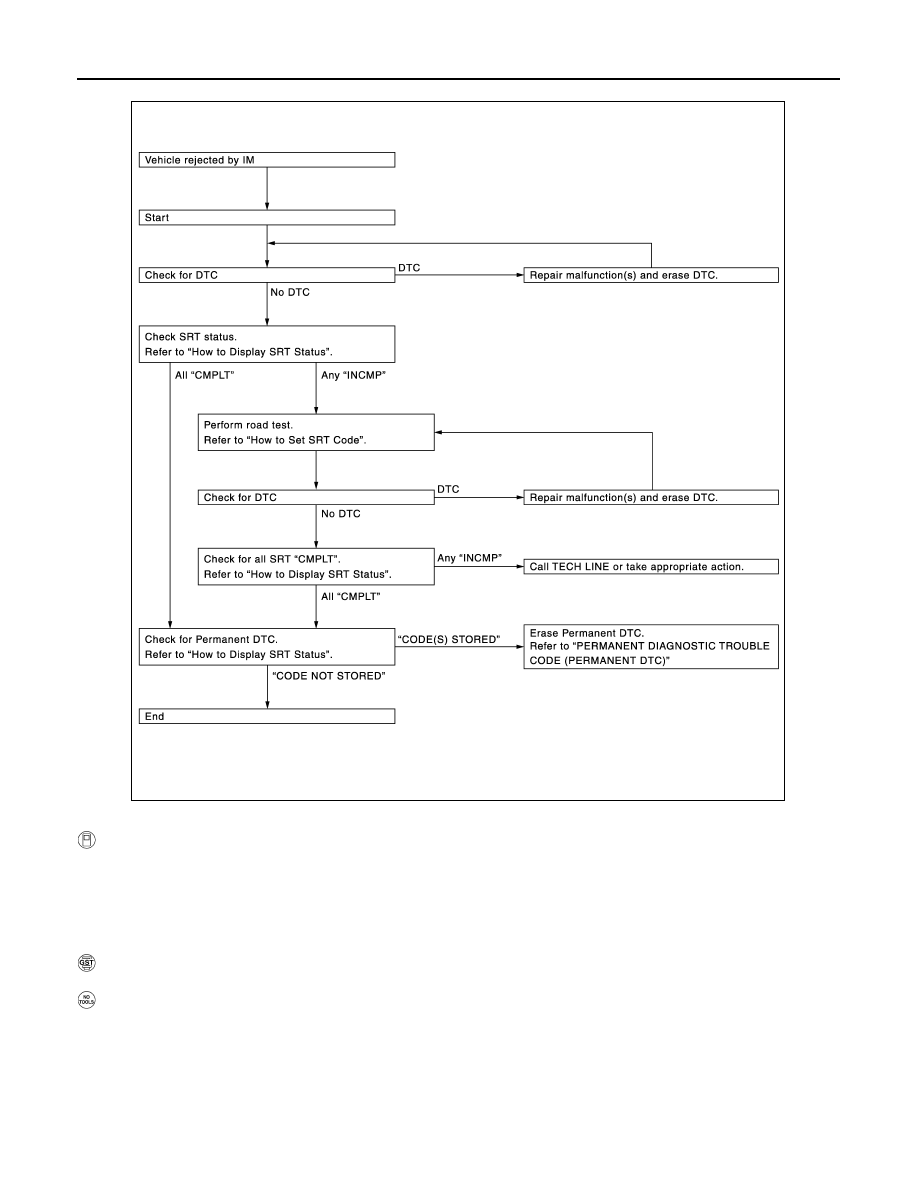
How to Display SRT Status

WITH CONSULT-III

Selecting “SRT STATUS” in “DTC CONFIRMATION” mode with CONSULT-III.

For items whose SRT codes are set, “CMPLT” is displayed on the CONSULT-III screen; for items whose SRT

codes are not set, “INCMP” is displayed.

NOTE:

• Though displayed on the CONSULT-III screen, “HO2S HTR” is not SRT item.

• “SRT STATUS” provides the presence or absence of permanent DTCs stored in ECM memory.

WITH GST

Selecting Service $01 with GST (Generic Scan Tool)

 NO TOOLS

A SRT code itself cannot be displayed, however SRT status can.
1. Turn ignition switch ON and wait 20 seconds.
2. SRT status is indicated as shown below.

• When all SRT codes are set, MIL illuminates continuously.

JSBIA0065GB

2010 Pathfinder

ECM

EC-469

< ECU DIAGNOSIS >

[VQ40DE]

C

D

E

F

G

H

I

J

K

L

M

A

EC

N

P

O

• When any SRT codes are not set, MIL will blink periodically for 10 seconds.

How to Set SRT Code

To set all SRT codes, self-diagnosis for the items indicated above must be performed one or more times. Each

diagnosis may require a long period of actual driving under various conditions.


WITH CONSULT-III

Perform corresponding DTC Confirmation Procedure one by one based on Performance Priority in the table

on "SRT Item".


WITHOUT CONSULT-III

The most efficient driving pattern in which SRT codes can be properly set is explained below. The driving pat-

tern should be performed one or more times to set all SRT codes.

JMBIA1515GB

2010 Pathfinder

EC-470

< ECU DIAGNOSIS >

[VQ40DE]

ECM

Driving Pattern

• The time required for each diagnosis varies with road surface conditions, weather, altitude, individual driving

habits, etc.

Zone A refers to the range where the time, required for the diagnosis under normal conditions*, is the short-

est.

Zone B refers to the range where the diagnosis can still be performed if the diagnosis is not completed within

zone A.

*: Normal conditions refer to the following:

JSBIA0162GB

2010 Pathfinder

ECM

EC-471

< ECU DIAGNOSIS >

[VQ40DE]

C

D

E

F

G

H

I

J

K

L

M

A

EC

N

P

O

• Sea level

• Flat road

• Ambient air temperature: 20 - 30

°

C (68 - 86

°

F)

• Diagnosis is performed as quickly as possible under normal conditions.

Under different conditions [For example: ambient air temperature other than 20 - 30

°

C (68 - 86

°

F)], diagno-

sis may also be performed.

Pattern 1:

The engine is started at the engine coolant temperature of 

10 to 35

°

C (14 to 95

°

F)

(where the voltage between the ECM terminal 73 and ground is 3.0 - 4.3V).

The engine must be operated at idle speed until the engine coolant temperature is greater than 70

°

C

(158

°

F) (where the voltage between the ECM terminal 73 and ground is lower than 1.4V).

The engine is started at the fuel tank temperature of warmer than 0

°

C (32

°

F) (where the voltage

between the ECM terminal 107 and ground is less than 4.1V).

Pattern 2:

• When steady-state driving is performed again even after it is interrupted, each diagnosis can be conducted.

In this case, the time required for diagnosis may be extended.

Pattern 3:

• Operate vehicle following the driving pattern shown in the figure.

• Replace the accelerator pedal during decelerating vehicle speed

from 90km/h (56MPH) to 0km/h (0MPH).

Pattern 4:

• Operate vehicle, following the driving pattern shown in the figure.

- Drive the vehicle in a proper gear at 60 km/h (38 MPH) and main-

tain the speed.

- Release the accelerator pedal fully at least 5 seconds.

- Repeat the above two steps at least 5 times.

Pattern 5:

• The accelerator pedal must be held very steady during steady-state driving.

• If the accelerator pedal is moved, the test must be conducted all over again.

*1: Depress the accelerator pedal until vehicle speed is 90 km/h (56 MPH), then release the accelerator pedal

and keep it released for more than 10 seconds. Depress the accelerator pedal until vehicle speed is 90 km/h

(56 MPH) again.

*2: Checking the vehicle speed with GST is advised.

Suggested Transmission Gear Position

Set the selector lever in the D position with the overdrive switch turned ON.

PERMANENT DIAGNOSTIC TROUBLE CODE (PERMANENT DTC)

Permanent DTC is defined in SAE J1979/ISO 15031-5 Service $0A.

ECM stores a DTC issuing a command of turning on MIL as a permanent DTC and keeps storing the DTC as

a permanent DTC until ECM judges that there is no presence of malfunction.

PBIB2244E

JSBIA0160GB

2010 Pathfinder

EC-472

< ECU DIAGNOSIS >

[VQ40DE]

ECM

Permanent DTCs cannot be erased by using the Erase function of CONSULT-III or Generic Scan Tool (GST)

and by disconnecting the battery to shut off power to ECM. This prevents a vehicle from passing the state

emission inspection without repairing a malfunctioning part.

When not passing the state emission inspection due to more than one permanent DTC, permanent DTCs

should be erased, referring to this manual.

NOTE:

• The important items in state emission inspection are that MIL is not ON, SRT test items are set, and perma-

nent DTCs are not included.

• Permanent DTCs do not apply for regions that permanent DTCs are not regulated by law.

Permanent DTC Item

For permanent DTC items, MIL turns ON. Refer to 

EC-464, "Emission-related Diagnostic Information"

, “EMIS-

SION-RELATED DIAGNOSTIC INFORMATION ITEMS”.

Permanent DTC Set Timing

The setting timing of permanent DTC is stored in ECM with the lighting of MIL when a DTC is confirmed.

Permanent DTC Service Procedure

How to Display Permanent DTC Status

WITH CONSULT-III

1. Turn ignition switch OFF and wait at least 10 seconds.

2. Turn ignition switch ON.

3. Turn ignition switch OFF and wait at least 10 seconds.

4. Turn ignition switch ON.

5. Select “PERMANENT DTC STATUS” in “DTC & SRT CONFIRMATION” mode with CONSULT-III.

NOTE:

Permanent DTCs stored in ECM memory are displayed on the CONSULT-III screen to show if a driving

pattern required for erasing permanent DTCs is complete (CMPLT) or incomplete (INCMP).

CAUTION:

JSBIA0066GB

2010 Pathfinder

ECM

EC-473

< ECU DIAGNOSIS >

[VQ40DE]

C

D

E

F

G

H

I

J

K

L

M

A

EC

N

P

O

Since the “PERMANENT DTC STATUS” screen displays the previous trip information, repeat the

following twice to update the information: “Ignition switch OFF”, “Wait for more than 10 seconds”

and “Ignition switch ON”.

WITH GST

1. Turn ignition switch OFF and wait at least 10 seconds.

2. Turn ignition switch ON.

3. Turn ignition switch OFF and wait at least 10 seconds.

4. Turn ignition switch ON.

5. Select Service $0A with GST (Generic Scan Tool).

TEST VALUE AND TEST LIMIT

The following is the information specified in Service $06 of SAE J1979/ISO 15031-5.

The test value is a parameter used to determine whether a system/circuit diagnostic test is OK or NG while

being monitored by the ECM during self-diagnosis. The test limit is a reference value which is specified as the

maximum or minimum value and is compared with the test value being monitored.

These data (test value and test limit) are specified by On Board Monitor ID(OBDMID), Test ID (TID), Unit and

Scaling ID and can be displayed on the GST screen.

The items of the test value and test limit will be displayed with GST screen which items are provided by the

ECM. (e.g., if bank 2 is not applied on this vehicle, only the items of bank 1 are displayed)

JSBIA0062GB

2010 Pathfinder

EC-474

< ECU DIAGNOSIS >

[VQ40DE]

ECM

Item

OBD-

MID

Self-diagnostic test item

DTC

Test value and Test 

limit

(GST display)

Description

TID

Unit and 

Scaling 

ID

HO2S

01H

Air fuel ratio (A/F) sensor 1 
(Bank 1)

P0131

83H

0BH

Minimum sensor output voltage for test 
cycle

P0131

84H

0BH

Maximum sensor output voltage for test 
cycle

P0130

85H

0BH

Minimum sensor output voltage for test 
cycle

P0130

86H

0BH

Maximum sensor output voltage for test 
cycle

P0133

87H

04H

Response rate: Response ratio (Lean to 
Rich)

P0133

88H

04H

Response rate: Response ratio (Rich to 
Lean)

P2A00

89H

84H

The amount of shift in air fuel ratio

P2A00

8AH

84H

The amount of shift in air fuel ratio

P0130

8BH

0BH

Difference in sensor output voltage

P0133

8CH

83H

Response gain at the limited frequency

P014C

8DH

04H

O2 Sensor Slow Response - Rich to 
Lean Bank 1 Sensor 1

P014C

8EH

04H

O2 Sensor Slow Response - Rich to 
Lean Bank 1 Sensor 1

P014D

8FH

84H

O2 Sensor Slow Response - Lean to 
Rich Bank 1 Sensor 1

P014D

90H

84H

O2 Sensor Slow Response - Lean to 
Rich Bank 1 Sensor 1

P015A

91H

01H

O2 Sensor Delayed Response - Rich to 
Lean Bank 1 Sensor 1

P015A

92H

01H

O2 Sensor Delayed Response - Rich to 
Lean Bank 1 Sensor 1

P015B

93H

01H

O2 Sensor Delayed Response - Lean to 
Rich Bank 1 Sensor 1

P015B

94H

01H

O2 Sensor Delayed Response - Lean to 
Rich Bank 1 Sensor 1

02H

Heated oxygen sensor 2 
(Bank 1)

P0138

07H

0CH

Minimum sensor output voltage for test 
cycle

P0137

08H

0CH

Maximum sensor output voltage for test 
cycle

P0138

80H

0CH

Sensor output voltage

P0139

81H

0CH

Difference in sensor output voltage

03H

Heated oxygen sensor 3 
(Bank 1)

P0143

07H

0CH

Minimum sensor output voltage for test 
cycle

P0144

08H

0CH

Maximum sensor output voltage for test 
cycle

P0146

80H

0CH

Sensor output voltage

P0145

81H

0CH

Difference in sensor output voltage

2010 Pathfinder

ECM

EC-475

< ECU DIAGNOSIS >

[VQ40DE]

C

D

E

F

G

H

I

J

K

L

M

A

EC

N

P

O

HO2S

05H

Air fuel ratio (A/F) sensor 1 
(Bank 2)

P0151

83H

0BH

Minimum sensor output voltage for test 
cycle

P0151

84H

0BH

Maximum sensor output voltage for test 
cycle

P0150

85H

0BH

Minimum sensor output voltage for test 
cycle

P0150

86H

0BH

Maximum sensor output voltage for test 
cycle

P0153

87H

04H

Response rate: Response ratio (Lean to 
Rich)

P0153

88H

04H

Response rate: Response ratio (Rich to 
Lean)

P2A03

89H

84H

The amount of shift in air fuel ratio

P2A03

8AH

84H

The amount of shift in air fuel ratio

P0150

8BH

0BH

Difference in sensor output voltage

P0153

8CH

83H

Response gain at the limited frequency

P014E

8DH

04H

O2 Sensor Slow Response - Rich to 
Lean Bank 2 Sensor 1

P014E

8EH

04H

O2 Sensor Slow Response - Rich to 
Lean Bank 2 Sensor 1

P014F

8FH

84H

O2 Sensor Slow Response - Lean to 
Rich Bank 2 Sensor 1

P014F

90H

84H

O2 Sensor Slow Response - Lean to 
Rich Bank 2 Sensor 1

P015C

91H

01H

O2 Sensor Delayed Response - Rich to 
Lean Bank 2 Sensor 1

P015C

92H

01H

O2 Sensor Delayed Response - Rich to 
Lean Bank 2 Sensor 1

P015D

93H

01H

O2 Sensor Delayed Response - Lean to 
Rich Bank 2 Sensor 1

P015D

94H

01H

O2 Sensor Delayed Response - Lean to 
Rich Bank 2 Sensor 1

06H

Heated oxygen sensor 2
(Bank 2)

P0158

07H

0CH

Minimum sensor output voltage for test 
cycle

P0157

08H

0CH

Maximum sensor output voltage for test 
cycle

P0158

80H

0CH

Sensor output voltage

P0159

81H

0CH

Difference in sensor output voltage

07H

Heated oxygen sensor 3 
(Bank2)

P0163

07H

0CH

Minimum sensor output voltage for test 
cycle

P0164

08H

0CH

Maximum sensor output voltage for test 
cycle

P0166

80H

0CH

Sensor output voltage

P0165

81H

0CH

Difference in sensor output voltage

Item

OBD-

MID

Self-diagnostic test item

DTC

Test value and Test 

limit

(GST display)

Description

TID

Unit and 

Scaling 

ID

2010 Pathfinder


Content      ..     295      296      297      298     ..