Nissan Pathfinder (2010 year). Manual - part 289


  Index      Manuals     Nissan Pathfinder (2010 year) - Service and Repair Manual


Search            copyright infringement  


Content      ..     287      288      289      290     ..


Nissan Pathfinder (2010 year). Manual - part 289


EC-404

< COMPONENT DIAGNOSIS >

[VQ40DE]

FUEL PUMP

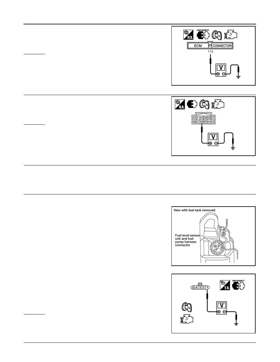
4. Check voltage between ECM terminal 113 and ground with

CONSULT-III or tester.

OK or NG

OK

>> GO TO 5.

NG

>> GO TO 3.

3.

CHECK FUEL PUMP POWER SUPPLY CIRCUIT-II

Check voltage between IPDM E/R terminal 46 and ground with

CONSULT-III or tester.

OK or NG

OK

>> GO TO 4.

NG

>> GO TO 12.

4.

DETECT MALFUNCTIONING PART

Check harness for open or short between IPDM E/R and ECM

>> Repair harness or connectors.

5.

CHECK FUEL PUMP POWER SUPPLY CIRCUIT-III

1. Turn ignition switch OFF.

2. Reconnect all harness connectors disconnected.

3. Disconnect “fuel level sensor unit and fuel pump” harness con-

nector.

4. Turn ignition switch ON.

5. Check voltage between “fuel level sensor unit and fuel pump”

terminal 1 and ground with CONSULT-III or tester. 

6. Also check harness for short to ground and short to power.
OK or NG

OK

>> GO TO 9.

NG

>> GO TO 6.

6.

CHECK 15A FUSE

1. Turn ignition switch OFF.

Voltage: Battery voltage 

PBIB1187E

Voltage: Battery voltage

PBIB2656E

BBIA0545E

Voltage:

Battery voltage should exist for 1 sec-
ond after ignition switch is turned ON.

PBIB0795E

2010 Pathfinder

FUEL PUMP

EC-405

< COMPONENT DIAGNOSIS >

[VQ40DE]

C

D

E

F

G

H

I

J

K

L

M

A

EC

N

P

O

2. Disconnect 15A fuse.

3. Check 15 A fuse (No.48).
OK or NG

OK

>> GO TO 7.

NG

>> Replace fuse.

7.

CHECK FUEL PUMP POWER SUPPLY CURCUIT-IV

1. Disconnect IPDM E/R harness connector E119.

2. Check harness continuity between “fuel level sensor unit and fuel pump” terminal 1 and IPDM E/R termi-

nal 13.

Refer to Wiring Diagram. 

3. Also check harness for short to ground and short to power.
OK or NG

OK

>> GO TO 12.

NG

>> GO TO 8.

8.

DETECT MALFUNCTIONING PART

Check the following.

• Harness connectors C1, E41

• Harness for open or short between “fuel level sensor unit and fuel pump” and IPDM E/R

>> Repair open circuit or short to ground or short to power in harness or connectors.

9.

CHECK FUEL PUMP GROUND CIRCUIT FOR OPEN AND SHORT

1. Check harness continuity between “fuel level sensor unit and fuel pump” terminal 3 and ground.

Refer to Wiring Diagram.

2. Also check harness for short to ground.
OK or NG

OK

>> GO TO 11.

NG

>> GO TO 10.

10.

DETECT MALFUNCTIONING PART

Check the following.

• Harness connectors C1, E41

• Harness for open or short between “fuel level sensor unit and fuel pump” and ground

>> Repair open circuit or short to power in harness or connectors.

11.

CHECK FUEL PUMP

Refer to 

EC-406, "Component Inspection"

.

OK or NG

OK

>> GO TO 12.

NG

>> Replace fuel pump.

12.

CHECK INTERMITTENT INCIDENT

Refer to 

GI-37, "Intermittent Incident"

.

OK or NG

OK

>> Replace IPDM E/R.

NG

>> Repair or replace harness or connectors.

Continuity should exist.

Continuity should exist.

2010 Pathfinder

EC-406

< COMPONENT DIAGNOSIS >

[VQ40DE]

FUEL PUMP

Component Inspection

INFOID:0000000005257443

FUEL PUMP

1. Disconnect “fuel level sensor unit and fuel pump” harness connector.
2. Check resistance between “fuel level sensor unit and fuel pump”

terminals 1 and 3.

Resistance: Approximately 0.2 - 5.0

 [at 25

°

C (77

°

F)]

SEC918C

2010 Pathfinder

IGNITION SIGNAL

EC-407

< COMPONENT DIAGNOSIS >

[VQ40DE]

C

D

E

F

G

H

I

J

K

L

M

A

EC

N

P

O

IGNITION SIGNAL

Component Description

INFOID:0000000005257444

IGNITION COIL & POWER TRANSISTOR

The ignition signal from the ECM is sent to and amplified by the power transistor. The power transistor turns

ON and OFF the ignition coil primary circuit. This ON/OFF operation induces the proper high voltage in the coil

secondary circuit.

Diagnosis Procedure

INFOID:0000000005257445

1.

CHECK ENGINE START

Turn ignition switch OFF, and restart engine.

Is engine running?

Yes or No

Yes (With CONSULT-III)>>GO TO 2.

Yes (Without CONSULT-III)>>GO TO 3.

No

>> GO TO 4.

2.

CHECK OVERALL FUNCTION


With CONSULT-III

1. Perform “POWER BALANCE” in “ACTIVE TEST” mode with CONSULT-III.

2. Make sure that each circuit produces a momentary engine speed drop.
OK or NG

OK

>>

INSPECTION END

NG

>> GO TO 10.

3.

CHECK OVERALL FUNCTION

 Without CONSULT-III

1. Let engine idle.

2. Read the voltage signal between ECM terminals 60, 61, 62, 79,

80, 81 and ground with an oscilloscope.

3. Verify that the oscilloscope screen shows the signal wave as

shown below.

NOTE:

The pulse cycle changes depending on rpm at idle.

OK or NG

OK

>>

INSPECTION END

NG

>> GO TO 10.

4.

CHECK IGNITION COIL POWER SUPPLY CIRCUIT-I

BBIA0561E

PBIB1186E

SEC986C

2010 Pathfinder

EC-408

< COMPONENT DIAGNOSIS >

[VQ40DE]

IGNITION SIGNAL

1. Turn ignition switch OFF, wait at least 10 seconds and then turn it ON.

2. Check voltage between ECM terminals 119, 120 and ground

with CONSULT-III or tester.

OK or NG

OK

>> GO TO 5.

NG

>> Go to 

EC-97, "Diagnosis Procedure"

.

5.

CHECK IGNITION COIL POWER SUPPLY CIRCUIT-II

1. Turn ignition switch OFF.

2. Disconnect condenser-1 harness connector.

3. Turn ignition switch ON.

4. Check voltage between condenser-1 terminal 1 and ground with

CONSULT-III or tester.

OK or NG

OK

>> GO TO 8.

NG

>> GO TO 6.

6.

CHECK IGNITION COIL POWER SUPPLY CIRCUIT-III

1. Turn ignition switch OFF.

2. Disconnect IPDM E/R harness connector E119.

3. Check harness continuity between IPDM E/R terminal 3 and condenser-1 terminal 1.

Refer to Wiring Diagram.

4. Also check harness for short to ground and short to power.
OK or NG

OK

>> GO TO 17.

NG

>> GO TO 7.

7.

DETECT MALFUNCTIONING PART

Check the following.

• Harness connectors E2, F32

• Harness for open or short between condenser-1 and IPDM E/R

>> Repair open circuit or short to ground or short to power in harness or connectors.

Voltage: Battery voltage

MBIB0034E

BBIA0562E

Voltage: Battery voltage

PBIB0624E

Continuity should exist.

2010 Pathfinder

IGNITION SIGNAL

EC-409

< COMPONENT DIAGNOSIS >

[VQ40DE]

C

D

E

F

G

H

I

J

K

L

M

A

EC

N

P

O

8.

CHECK CONDENSER-1 GROUND CIRCUIT FOR OPEN AND SHORT

1. Turn ignition switch OFF.

2. Check harness continuity between condenser-1 terminal 2 and ground.

Refer to Wiring Diagram.

3. Also check harness for short to power.
OK or NG

OK

>> GO TO 9.

NG

>> Repair open circuit or short to power in harness or connectors.

9.

CHECK CONDENSER-1

Refer to 

EC-410, "Component Inspection"

.

OK or NG

OK

>> GO TO 10.

NG

>> Replace condenser-1.

10.

CHECK IGNITION COIL POWER SUPPLY CIRCUIT-V

1. Turn ignition switch OFF.

2. Reconnect all harness connectors disconnected.

3. Disconnect ignition coil harness connector.

4. Turn ignition switch ON.

5. Check voltage between ignition coil terminal 3 and ground with

CONSULT-III or tester.

OK or NG

OK

>> GO TO 12.

NG

>> GO TO 11.

11.

DETECT MALFUNCTIONING PART

Check the following.

• Harness connectors F26, F225

• Harness for open or short between ignition coil and harness connector F32

>> Repair or replace harness or connectors.

12.

CHECK IGNITION COIL GROUND CIRCUIT FOR OPEN AND SHORT

1. Turn ignition switch OFF.

2. Check harness continuity between ignition coil terminal 2 and ground.

Refer to Wiring Diagram.

Continuity should exist.

Voltage: Battery voltage

BBIA0561E

PBIB0138E

Continuity should exist.

2010 Pathfinder

EC-410

< COMPONENT DIAGNOSIS >

[VQ40DE]

IGNITION SIGNAL

3. Also check harness for short to power.
OK or NG

OK

>> GO TO 14.

NG

>> GO TO 13.

13.

DETECT MALFUNCTIONING PART

Check the following.

• Harness connectors F225, F26

• Harness for open or short between ignition coil and ground

>> Repair open circuit or short to power in harness or connectors.

14.

CHECK IGNITION COIL OUTPUT SIGNAL CIRCUIT FOR OPEN AND SHORT

1. Disconnect ECM harness connector.

2. Check harness continuity between ECM terminals 60, 61, 62, 79, 80, 81 and ignition coil terminal 1.

Refer to Wiring Diagram.

3. Also check harness for short to ground and short to power.
OK or NG

OK

>> GO TO 16.

NG

>> GO TO 15.

15.

DETECT MALFUNCTIONING PART

Check the following.

• Harness connectors F26, F225

• Harness for open or short between ignition coil and ECM

>> Repair open circuit or short to ground or short to power in harness or connectors.

16.

CHECK IGNITION COIL WITH POWER TRANSISTOR

Refer to 

EC-410, "Component Inspection"

.

OK or NG

OK

>> GO TO 17.

NG

>> Replace malfunctioning ignition coil with power transistor.

17.

CHECK INTERMITTENT INCIDENT

Refer to 

GI-37, "Intermittent Incident"

.

>>

INSPECTION END

Component Inspection

INFOID:0000000005257446

IGNITION COIL WITH POWER TRANSISTOR

CAUTION:

Do the following procedure in the place where ventilation is good without the combustible.

1. Turn ignition switch OFF.

2. Disconnect ignition coil harness connector.

Continuity should exist.

2010 Pathfinder

IGNITION SIGNAL

EC-411

< COMPONENT DIAGNOSIS >

[VQ40DE]

C

D

E

F

G

H

I

J

K

L

M

A

EC

N

P

O

3. Check resistance between ignition coil terminals as follows.

4. If NG, Replace ignition coil with power transistor.

If OK, go to next step.

5. Turn ignition switch OFF.

6. Reconnect all harness connectors disconnected.

7. Remove fuel pump fuse (No.48) in IPDM E/R to release fuel

pressure.

NOTE:

Do not use CONSULT-III to release fuel pressure, or fuel pres-

sure applies again during the following procedure.

8. Start engine.

9. After engine stalls, crank it two or three times to release all fuel

pressure.

10. Turn ignition switch OFF.

11. Remove ignition coil harness connectors to avoid the electrical

discharge from the ignition coils.

12. Remove ignition coil and spark plug of the cylinder to be

checked.

13. Crank engine for five seconds or more to remove combustion gas in the cylinder.

14. Connect spark plug and harness connector to ignition coil.

15. Fix ignition coil using a rope etc. with gap of 13 - 17 mm (0.52 -

0.66 in) between the edge of the spark plug and grounded metal

portion as shown in the figure.

16. Crank engine for about three seconds, and check whether spark

is generated between the spark plug and the grounded part.

CAUTION:

• Never place to the spark plug and the ignition coil within

50cm (19.7 in) each other. Be careful not to get an electri-

cal shock while checking, because the electrical dis-

charge voltage becomes 20 kV or more.

• It might cause to damage the ignition coil if the gap of more than 17 mm (0.66 in) is made.

NOTE:

When the gap is less than 13 mm (0.52 in), the spark might be generated even if the coil is mal-

functioning.

17. If NG, Replace ignition coil with power transistor.

CONDENSER-1

1. Turn ignition switch OFF.

2. Disconnect condenser-1 harness connector.

3. Check resistance between condenser-1 terminals 1 and 2.

Terminal No. (Polarity)

Resistance 

 [at 25

°

C (77

°

F)]

1 and 2

Except 0 or 

1 and 3

Except 0

2 and 3

Spark should be generated.

PBIB0847E

BBIA0534E

JMBIA0066GB

Resistance

Above 1 M

 at 25

°

C (77

°

F)

PBIB0794E

2010 Pathfinder


Content      ..     287      288      289      290     ..