Nissan Pathfinder (2010 year). Manual - part 288
EC-396
< COMPONENT DIAGNOSIS >
[VQ40DE]
COOLING FAN
4.
CHECK COOLING FAN MOTOR
EC-396, "Component Inspection"
OK or NG
OK
>> GO TO 5.
NG
>> Replace cooling fan motor.
5.
CHECK INTERMITTENT INCIDENT
Perform
GI-37, "Intermittent Incident"
.
OK or NG
OK
>> INSPETION END
NG
>> Repair or replace harness or connector.
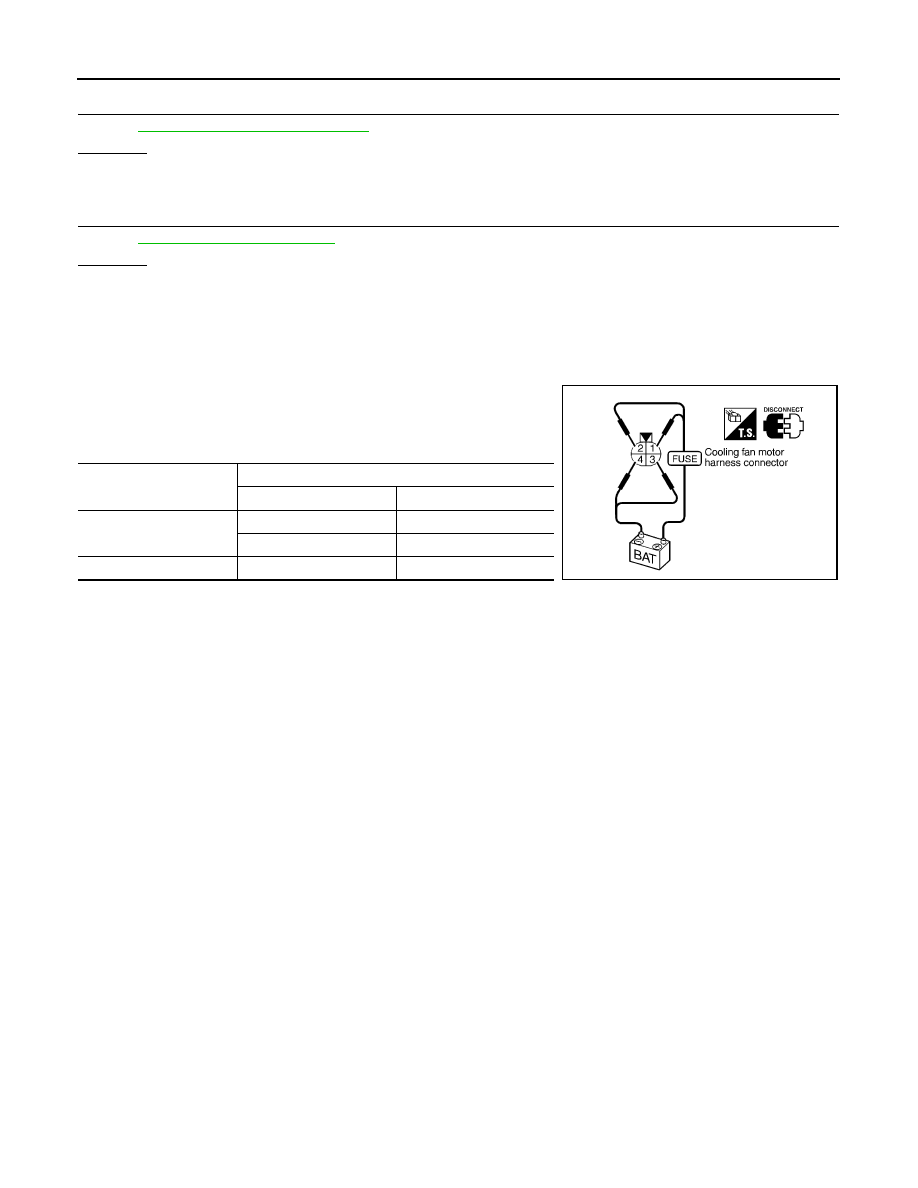
Component Inspection
INFOID:0000000005257435
COOLING FAN MOTOR
1. Disconnect cooling fan motor harness connectors.
2. Supply cooling fan motor terminals with battery voltage and
check operation.
Cooling fan motor should operate.
If NG, replace cooling fan motor.
Cooling fan speed
Cooling fan motor terminals
(+)
(
−
)
Low
1
3 and 4
2
3 and 4
High
1 and 2
3 and 4
SEF734W
2010 Pathfinder