Nissan Pathfinder (2010 year). Manual - part 274


  Index      Manuals     Nissan Pathfinder (2010 year) - Service and Repair Manual


Search            copyright infringement  


Content      ..     272      273      274      275     ..


Nissan Pathfinder (2010 year). Manual - part 274


EC-284

< COMPONENT DIAGNOSIS >

[VQ40DE]

P0456 EVAP CONTROL SYSTEM

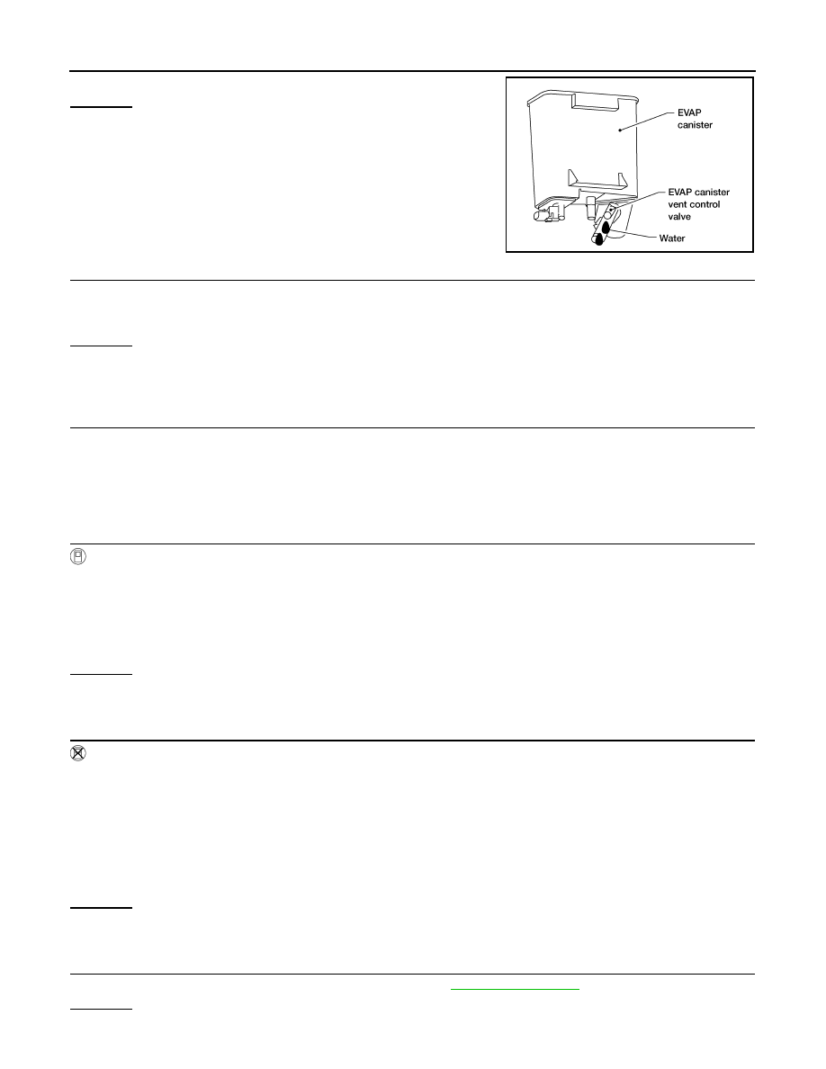
2. Does water drain from the EVAP canister?
Yes or No

Yes

>> GO TO 10.

No (With CONSULT-III)>>GO TO 12.

No (Without CONSULT-III)>>GO TO 13.

10.

CHECK EVAP CANISTER

Weigh the EVAP canister with the EVAP canister vent control valve and EVAP control system pressure sensor

attached.

The weight should be less than 2.0 kg (4.4 lb).

OK or NG

OK (With CONSULT-III)>>GO TO 12.

OK (Without CONSULT-III)>>GO TO 13.

NG

>> GO TO 11.

11.

DETECT MALFUNCTIONING PART

Check the following.

• EVAP canister for damage

• EVAP hose between EVAP canister and vehicle frame for clogging or poor connection

>> Repair hose or replace EVAP canister.

12.

CHECK EVAP CANISTER PURGE VOLUME CONTROL SOLENOID VALVE OPERATION


With CONSULT-III

1. Disconnect vacuum hose connected to EVAP service port and EVAP canister purge volume control sole-

noid valve from EVAP canister purge volume control solenoid valve.

2. Start engine.

3. Perform “PURG VOL CONT/V” in “ACTIVE TEST” mode.

4. Touch “Qu” on CONSULT-III screen to increase “PURG VOL CONT/V” opening to 100%.

5. Check vacuum hose for vacuum when revving engine up to 2,000 rpm.
OK or NG

OK

>> GO TO 16.

NG

>> GO TO 14.

13.

CHECK EVAP CANISTER PURGE VOLUME CONTROL SOLENOID VALVE OPERATION


Without CONSULT-III

1. Start engine and warm it up to normal operating temperature.

2. Stop engine.

3. Disconnect vacuum hose connected to EVAP service port and EVAP canister purge volume control sole-

noid valve from EVAP canister purge volume control solenoid valve.

4. Start engine and let it idle for at least 80 seconds.

5. Check vacuum hose for vacuum when revving engine up to 2,000 rpm.

OK or NG

OK

>> GO TO 15.

NG

>> GO TO 14.

14.

CHECK VACUUM HOSE

Check vacuum hoses for clogging or disconnection. Refer to 

EC-45, "Description"

.

OK or NG

OK

>> GO TO 15.

BBIA0558E

Vacuum should exist.

2010 Pathfinder

P0456 EVAP CONTROL SYSTEM

EC-285

< COMPONENT DIAGNOSIS >

[VQ40DE]

C

D

E

F

G

H

I

J

K

L

M

A

EC

N

P

O

NG

>> Repair or reconnect the hose.

15.

CHECK EVAP CANISTER PURGE VOLUME CONTROL SOLENOID VALVE

Refer to 

EC-250, "Component Inspection"

.

OK or NG

OK

>> GO TO 16.

NG

>> Replace EVAP canister purge volume control solenoid valve.

16.

CHECK FUEL TANK TEMPERATURE SENSOR

Refer to 

EC-200, "Component Inspection"

.

OK or NG

OK

>> GO TO 17.

NG

>> Replace fuel level sensor unit.

17.

CHECK EVAP CONTROL SYSTEM PRESSURE SENSOR

Refer to 

EC-266, "Component Inspection"

.

OK or NG

OK

>> GO TO 18.

NG

>> Replace EVAP control system pressure sensor.

18.

CHECK EVAP PURGE LINE

Check EVAP purge line (pipe, rubber tube, fuel tank and EVAP canister) for cracks or improper connection.

Refer to 

EC-45, "Description"

.

OK or NG

OK

>> GO TO 19.

NG

>> Repair or reconnect the hose.

19.

CLEAN EVAP PURGE LINE

Clean EVAP purge line (pipe and rubber tube) using air blower.

>> GO TO 20.

20.

CHECK EVAP/ORVR LINE

Check EVAP/ORVR line between EVAP canister and fuel tank for clogging, kinks, looseness and improper

connection. For location, refer to 

EC-412, "System Description"

.

OK or NG

OK

>> GO TO 21.

NG

>> Repair or replace hoses and tubes.

21.

CHECK RECIRCULATION LINE

Check recirculation line between filler neck tube and fuel tank for clogging, kinks, cracks, looseness and

improper connection.
OK or NG

OK

>> GO TO 22.

NG

>> Repair or replace hose, tube or filler neck tube.

22.

CHECK REFUELING EVAP VAPOR CUT VALVE

Refer to 

EC-415, "Component Inspection"

.

OK or NG

OK

>> GO TO 23.

NG

>> Replace refueling EVAP vapor cut valve with fuel tank. 

23.

CHECK FUEL LEVEL SENSOR

Refer to 

MWI-33, "Component Inspection"

.

OK or NG

OK

>> GO TO 24.

NG

>> Replace fuel level sensor unit.

2010 Pathfinder

EC-286

< COMPONENT DIAGNOSIS >

[VQ40DE]

P0456 EVAP CONTROL SYSTEM

24.

CHECK INTERMITTENT INCIDENT

Refer to 

GI-37, "Intermittent Incident"

.

>>

INSPECTION END

Component Inspection

INFOID:0000000005257263

FUEL TANK VACUUM RELIEF VALVE (BUILT INTO FUEL FILLER CAP)

1. Wipe clean valve housing.

2. Check valve opening pressure and vacuum.

3. If out of specification, replace fuel filler cap as an assembly.

CAUTION:

Use only a genuine fuel filler cap as a replacement. If an incor-

rect fuel filler cap is used, the MIL may come on.

SEF445Y

Pressure: 15.3 - 20.0 kPa (0.156 - 0.204 kg/cm

2

, 2.22 - 

2.90 psi)

Vacuum:

6.0 to 

3.3 kPa (

0.061 to 

0.034 kg/cm

2

0.87 to 

0.48 psi)

SEF943S

2010 Pathfinder

P0460 FUEL LEVEL SENSOR

EC-287

< COMPONENT DIAGNOSIS >

[VQ40DE]

C

D

E

F

G

H

I

J

K

L

M

A

EC

N

P

O

P0460 FUEL LEVEL SENSOR

Component Description

INFOID:0000000005257264

The fuel level sensor is mounted in the fuel level sensor unit. The

sensor detects a fuel level in the fuel tank and transmits a signal to

the combination meter. The combination meter sends the fuel level

sensor signal to the ECM through the CAN communication line.

It consists of two parts, one is mechanical float and the other is vari-

able resistor. Fuel level sensor output voltage changes depending on

the movement of the fuel mechanical float.

On Board Diagnosis Logic

INFOID:0000000005257265

NOTE:

If DTC P0460 is displayed with DTC UXXXX, first perform the trouble diagnosis for DTC UXXXX.

If DTC P0460 is displayed with DTC P0607, first perform the trouble diagnosis for DTC P0607.


Refer

to 

EC-308, "Description"

.

When the vehicle is parked, the fuel level in the fuel tank is naturally stable. It means that output signal of the

fuel level sensor does not change. If ECM senses sloshing signal from the sensor, fuel level sensor malfunc-

tion is detected.

DTC Confirmation Procedure

INFOID:0000000005257266

1. If DTC Confirmation Procedure has been previously conducted, always perform the following before con-

ducting the next step.

a. Turn ignition switch OFF and wait at least 10 seconds.
b. Turn ignition switch ON.
c. Turn ignition switch OFF and wait at least 10 seconds.
2. Start engine and wait maximum of 2 consecutive minutes.
3. Check 1st trip DTC.
4. If 1st trip DTC is detected, go to 

EC-287, "Diagnosis Procedure"

.

Diagnosis Procedure

INFOID:0000000005257267

1.

CHECK COMBINATION METER FUNCTION

Refer to 

GI-33, "Work Flow"

.

OK or NG

OK

>> GO TO 2.

NG

>> Go to 

MWI-32, "Component Function Check"

.

2.

CHECK INTERMITTENT INCIDENT

Refer to 

GI-37, "Intermittent Incident"

.

BBIA0529E

DTC No.

Trouble diagnosis name

DTC detecting condition

Possible cause

P0460
0460

Fuel level sensor circuit 
noise

Even though the vehicle is parked, a signal be-
ing varied is sent from the fuel level sensor to 
ECM.

• Harness or connectors

(The CAN communication line is open or 
shorted)

• Harness or connectors

(The sensor circuit is open or shorted)

• Combination meter
• Fuel level sensor

2010 Pathfinder

EC-288

< COMPONENT DIAGNOSIS >

[VQ40DE]

P0460 FUEL LEVEL SENSOR

>>

INSPECTION END

2010 Pathfinder

P0461 FUEL LEVEL SENSOR

EC-289

< COMPONENT DIAGNOSIS >

[VQ40DE]

C

D

E

F

G

H

I

J

K

L

M

A

EC

N

P

O

P0461 FUEL LEVEL SENSOR

Component Description

INFOID:0000000005257268

The fuel level sensor is mounted in the fuel level sensor unit. The

sensor detects a fuel level in the fuel tank and transmits a signal to

the combination meter. The combination meter sends the fuel level

sensor signal to the ECM through CAN communication line.

It consists of two parts, one is mechanical float and the other is vari-

able resistor. Fuel level sensor output voltage changes depending on

the movement of the fuel mechanical float.

On Board Diagnosis Logic

INFOID:0000000005257269

NOTE:

If DTC P0461 is displayed with DTC UXXXX, first perform the trouble diagnosis for DTC UXXXX.

If DTC P0461 is displayed with DTC P0607, first perform the trouble diagnosis for DTC P0607. Refer

to 

EC-308, "Description"

.

Driving long distances naturally affect fuel gauge level.

This diagnosis detects the fuel gauge malfunction of the gauge not moving even after a long distance has

been driven.

Overall Function Check

INFOID:0000000005257270

Use this procedure to check the overall function of the fuel level sensor. During this check, a 1st trip DTC

might not be confirmed.

WARNING:

When performing the following procedure, always observe the handling of the fuel. Refer to 

FL-11,

"Removal and Installation"

.

TESTING CONDITION:

Before starting overall function check, preparation of draining fuel and refilling fuel is required.

 WITH CONSULT-III

NOTE:
Start from step 10, if it is possible to confirm that the fuel cannot be drained by 30   (7-7/8 US gal, 6-5/

8 Imp gal) in advance.

1. Prepare a fuel container and a spare hose.

2. Release fuel pressure from fuel line, refer to 

EC-495, "Fuel Pressure Check"

.

3. Remove the fuel feed hose on the fuel level sensor unit.

4. Connect a spare fuel hose where the fuel feed hose was removed.

5. Turn ignition switch OFF and wait at least 10 seconds then turn ON.

6. Select “FUEL LEVEL SE” in “DATA MONITOR” mode with CONSULT-III.

7. Check “FUEL LEVEL SE” output voltage and note it.

8. Select “FUEL PUMP” in “ACTIVE TEST” mode with CONSULT-III.
9. Touch ON and drain fuel approximately 30   (7-7/8 US gal, 6-5/8 Imp gal) and stop it.

10. Check “FUEL LEVEL SE” output voltage and note it.
11. Fill fuel into the fuel tank for 30   (7-7/8 US gal, 6-5/8 Imp gal).

12. Check “FUEL LEVEL SE” output voltage and note it.

BBIA0529E

DTC No.

Trouble diagnosis name

DTC detecting condition

Possible cause

P0461
0461

Fuel level sensor circuit 
range/performance

The output signal of the fuel level sensor does 
not change within the specified range even 
though the vehicle has been driven a long dis-
tance.

• Harness or connectors

(The CAN communication line is open or 
shorted)

• Harness or connectors

(The sensor circuit is open or shorted)

• Combination meter
• Fuel level sensor

2010 Pathfinder

EC-290

< COMPONENT DIAGNOSIS >

[VQ40DE]

P0461 FUEL LEVEL SENSOR

13. Confirm whether the voltage changes more than 0.03V during step 7 to 10 and 10 to 12.

If NG, go to 

EC-290, "Diagnosis Procedure"

.

 WITH GST

NOTE:
Start from step 8, if it is possible to confirm that the fuel cannot be drained by 30   (7-7/8 US gal, 6-5/8

Imp gal) in advance.

1. Prepare a fuel container and a spare hose.

2. Release fuel pressure from fuel line. Refer to 

EC-495, "Fuel Pressure Check"

.

3. Remove the fuel feed hose on the fuel level sensor unit.

4. Connect a spare fuel hose where the fuel feed hose was removed.

5. Turn ignition switch ON.
6. Drain fuel by 30   (7-7/8 US gal, 6-5/8 Imp gal) from the fuel tank using proper equipment.

7. Confirm that the fuel gauge indication varies.
8. Fill fuel into the fuel tank for 30   (7-7/8 US gal, 6-5/8 Imp gal).

9. Confirm that the fuel gauge indication varies.

10. If NG, go to 

EC-290, "Diagnosis Procedure"

.

Diagnosis Procedure

INFOID:0000000005257271

1.

CHECK COMBINATION METER FUNCTION

Refer to 

GI-33, "Work Flow"

.

OK or NG

OK

>> GO TO 2.

NG

>> Go to 

MWI-32, "Component Function Check"

.

2.

CHECK INTERMITTENT INCIDENT

Refer to 

GI-37, "Intermittent Incident"

.

>>

INSPECTION END

2010 Pathfinder

P0462, P0463 FUEL LEVEL SENSOR

EC-291

< COMPONENT DIAGNOSIS >

[VQ40DE]

C

D

E

F

G

H

I

J

K

L

M

A

EC

N

P

O

P0462, P0463 FUEL LEVEL SENSOR

Component Description

INFOID:0000000005257272

The fuel level sensor is mounted in the fuel level sensor unit. The

sensor detects a fuel level in the fuel tank and transmits a signal to

the combination meter. The combination meter sends the fuel level

sensor signal to the ECM through CAN communication line.

It consists of two parts, one is mechanical float and the other is vari-

able resistor. Fuel level sensor output voltage changes depending on

the movement of the fuel mechanical float.

On Board Diagnosis Logic

INFOID:0000000005257273

NOTE:

If DTC P0462 or P0463 is displayed with DTC UXXXX, first perform the trouble diagnosis for DTC

UXXXX.

If DTC P0462 or P0463 is displayed with DTC P0607, first perform the trouble diagnosis for DTC

P0607. Refer to 

EC-308, "Description"

.

DTC Confirmation Procedure

INFOID:0000000005257274

NOTE:

If DTC Confirmation Procedure has been previously conducted, always perform the following before conduct-

ing the next step.

1. Turn ignition switch OFF and wait at least 10 seconds.

2. Turn ignition switch ON.

3. Turn ignition switch OFF and wait at least 10 seconds.

TESTING CONDITION:

Before performing the following procedure, confirm that battery voltage is more than 11V at ignition

switch ON.

1. Turn ignition switch ON and wait at least 5 seconds.

2. Check 1st trip DTC.

3. If 1st trip DTC is detected, go to 

EC-291, "Diagnosis Procedure"

.

Diagnosis Procedure

INFOID:0000000005257275

1.

CHECK COMBINATION METER FUNCTION

Refer to 

GI-33, "Work Flow"

.

OK or NG

OK

>> GO TO 2.

NG

>> Go to 

MWI-32, "Component Function Check"

.

2.

CHECK INTERMITTENT INCIDENT

Refer to 

GI-37, "Intermittent Incident"

.

BBIA0529E

DTC No.

Trouble diagnosis name

DTC detecting condition

Possible cause

P0462
0462

Fuel level sensor circuit 
low input

An excessively low voltage from the sensor is 
sent to ECM.

• Harness or connectors

(The CAN communication line is open or 
shorted)

• Harness or connectors

(The sensor circuit is open or shorted)

• Combination meter
• Fuel level sensor

P0463
0463

Fuel level sensor circuit 
high input

An excessively high voltage from the sensor is 
sent to ECM.

2010 Pathfinder


Content      ..     272      273      274      275     ..