Nissan Pathfinder (2010 year). Manual - part 267
EC-228
< COMPONENT DIAGNOSIS >
[VQ40DE]
P0420, P0430 THREE WAY CATALYST FUNCTION
NG
>> Repair or replace.
4.
CHECK IGNITION TIMING
Check the following items. Refer to
OK or NG
OK
>> GO TO 5.
NG
>> Follow the
5.
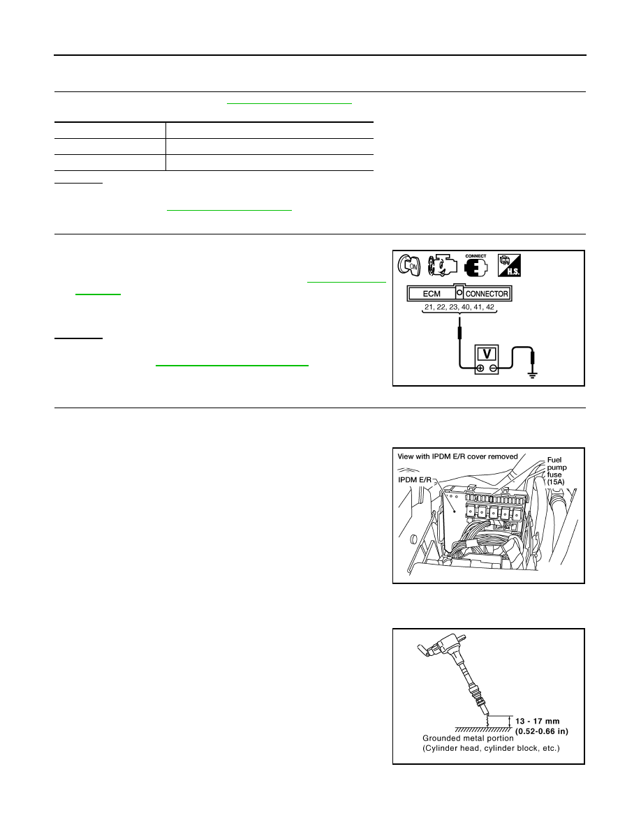
CHECK FUEL INJECTOR
1. Stop engine and then turn ignition switch ON.
2. Check voltage between ECM terminals 21, 22, 23, 40, 41, 42
and ground with CONSULT-III or tester.
Refer to Wiring Diagram for FUEL INJECTOR,
OK or NG
OK
>> GO TO 6.
NG
>> Perform
.
6.
CHECK FUNCTION OF IGNITION COIL-I
CAUTION:
Perform the following procedure in a place with no combustible objects and good ventilation.
1. Turn ignition switch OFF.
2. Remove fuel pump fuse (No.48) in IPDM E/R to release fuel
pressure.
NOTE:
Never use CONSULT-III to release fuel pressure, or fuel pres-
sure applies again during the following procedure.
3. Start engine.
4. After engine stalls, crank it two or three times to release all fuel
pressure.
5. Turn ignition switch OFF.
6. Remove all ignition coil harness connectors to avoid the electri-
cal discharge from the ignition coils.
7. Remove ignition coil and spark plug of the cylinder to be
checked.
8. Crank engine for five seconds or more to remove combustion gas in the cylinder.
9. Connect spark plug and harness connector to ignition coil.
10. Fix ignition coil using a rope etc. with gap of 13 - 17 mm (0.52 -
0.66 in) between the edge of the spark plug and grounded metal
portion as shown in the figure.
11. Crank engine for about three seconds, and check whether spark
is generated between the spark plug and the grounded metal
portion.
CAUTION:
• Never place to the spark plug and the ignition coil within
50 cm (19.7 in) each other. Be careful not to get an electri-
cal shock while checking, because the electrical dis-
charge voltage becomes 20 kV or more.
Items
Specifications
Target idle speed
625
±
50 rpm (in P or N position)
Ignition timing
15
±
5
°
BTDC (in P or N position)
Battery voltage should exist.
PBIB1172E
Spark should be generated.
BBIA0534E
JMBIA0066GB
2010 Pathfinder