Nissan Pathfinder (2010 year). Manual - part 265


  Index      Manuals     Nissan Pathfinder (2010 year) - Service and Repair Manual


Search            copyright infringement  


Content      ..     263      264      265      266     ..


Nissan Pathfinder (2010 year). Manual - part 265


EC-212

< COMPONENT DIAGNOSIS >

[VQ40DE]

P0300, P0301, P0302, P0303, P0304, P0305, P0306 MISFIRE

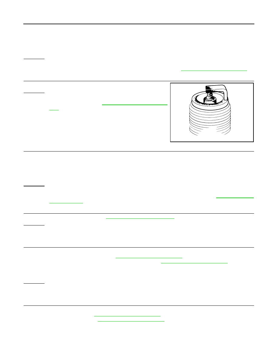
2. Disconnect spark plug and connect a known-good spark plug.

3. Crank engine for about three seconds, and recheck whether spark is generated between the spark plug

and the grounded metal portion.

OK or NG

OK

>> GO TO 9.

NG

>> Check ignition coil, power transistor and their circuits. Refer to 

EC-407, "Diagnosis Procedure"

.

9.

CHECK SPARK PLUG

Check the initial spark plug for fouling, etc.
OK or NG

OK

>> Replace spark plug(s) with standard type one(s). For

spark plug type, refer to 

EM-17, "Removal and Installa-

tion"

.

NG

>> 1. Repair or clean spark plug.

2. GO TO 10.

10.

CHECK FUNCTION OF IGNITION COIL-III

1. Reconnect the initial spark plugs.

2. Crank engine for about three seconds, and recheck whether spark is generated between the spark plug

and the grounded portion.

OK or NG

OK

>>

INSPECTION END

NG

>> Replace spark plug(s) with standard type one(s). For spark plug type, refer to 

EM-17, "Removal

and Installation"

.

11.

CHECK COMPRESSION PRESSURE

Check compression pressure. Refer to 

EM-23, "Compression Pressure"

.

OK or NG

OK

>> GO TO 12.

NG

>> Check pistons, piston rings, valves, valve seats and cylinder head gaskets.

12.

CHECK FUEL PRESSURE

1. Install all removed parts.

2. Release fuel pressure to zero. Refer to 

EC-495, "Fuel Pressure Check"

.

3. Install fuel pressure gauge and check fuel pressure. Refer to 

EC-495, "Fuel Pressure Check"

.

OK or NG

OK

>> GO TO 14.

NG

>> GO TO 13.

13.

DETECT MALFUNCTIONING PART

Check the following.

• Fuel pump and circuit (Refer to 

EC-399, "Diagnosis Procedure"

.)

• Fuel pressure regulator (Refer to 

EC-495, "Fuel Pressure Check"

.)

• Fuel lines

• Fuel filter for clogging

>> Repair or replace.

Spark should be generated.

SEF156I

Spark should be generated.

At idle: Approx. 350 kPa (3.57 kg/cm

2

, 51 psi)

2010 Pathfinder

P0300, P0301, P0302, P0303, P0304, P0305, P0306 MISFIRE

EC-213

< COMPONENT DIAGNOSIS >

[VQ40DE]

C

D

E

F

G

H

I

J

K

L

M

A

EC

N

P

O

14.

CHECK IGNITION TIMING

Check the following items. Refer to 

EC-20, "Basic Inspection"

.

OK or NG

OK

>> GO TO 15.

NG

>> Follow the 

EC-20, "Basic Inspection"

.

15.

CHECK A/F SENSOR 1 INPUT SIGNAL

1. Turn ignition switch OFF.

2. Disconnect A/F sensor 1 harness connector.

3. Disconnect ECM harness connector.

4. Check harness continuity between A/F sensor 1 terminal and ECM terminal as follows.

Refer to Wiring Diagram.

5. Check harness continuity between the following terminals and ground.

Refer to Wiring Diagram.

6. Also check harness for short to power.
OK or NG

OK

>> GO TO 16.

NG

>> Repair open circuit or short to ground or short to power in harness or connectors between ECM

and A/F sensor 1.

16.

CHECK A/F SENSOR 1 HEATER

Refer to 

EC-108, "Component Inspection"

.

OK or NG

Items

Specifications

Target idle speed

625 

±

 50 rpm (in P or N position)

Ignition timing

15 

±

 5

°

 BTDC (in P or N position)

A/F sensor 1 terminal

ECM terminal

Bank 1

1

16

2

75

Bank 2

1

35

2

56

Continuity should exist.

Bank 1

Bank 2

A/F sensor 1 terminal

ECM terminal

A/F sensor 1 terminal

ECM terminal

1

16

1

35

2

75

2

56

Continuity should not exist.

BBIA0544E

2010 Pathfinder

EC-214

< COMPONENT DIAGNOSIS >

[VQ40DE]

P0300, P0301, P0302, P0303, P0304, P0305, P0306 MISFIRE

OK

>> GO TO 18.

NG

>> GO TO 17.

17.

REPLACE A/F SENSOR 1

Replace malfunctioning A/F sensor 1.

CAUTION:

• Discard any A/F sensor which has been dropped from a height of more than 0.5 m (19.7 in) onto a

hard surface such as a concrete floor; use a new one.

• Before installing new A/F sensor, clean exhaust system threads using Heated Oxygen Sensor

Thread Cleaner tool J-43897-18 or J-43897-12 and approved anti-seize lubricant.

>>

INSPECTION END

18.

CHECK MASS AIR FLOW SENSOR


With CONSULT-III

Check mass air flow sensor signal in “DATA MONITOR” mode with CONSULT-III.


With GST

Check mass air flow sensor signal in Service $01 with GST.

OK or NG

OK

>> GO TO 19.

NG

>> Check connectors for rusted terminals or loose connections in the mass air flow sensor circuit or

ground. Refer to 

EC-120, "Component Inspection"

.

19.

CHECK SYMPTOM MATRIX CHART

Check items on the rough idle symptom in 

EC-484, "Symptom Matrix Chart"

.

OK or NG

OK

>> GO TO 20.

NG

>> Repair or replace.

20.

ERASE THE 1ST TRIP DTC

Some tests may cause a 1st trip DTC to be set.

Erase the 1st trip DTC from the ECM memory after performing the tests. Refer to 

EC-53, "Emission-related

Diagnostic Information"

.

>> GO TO 21.

21.

CHECK INTERMITTENT INCIDENT

Refer to 

GI-37, "Intermittent Incident"

.

>>

INSPECTION END

2.0 - 6.0 g·m/sec:

at idling

7.0 - 20.0 g·m/sec:

at 2,500 rpm

2.0 - 6.0 g·m/sec:

at idling

7.0 - 20.0 g·m/sec:

at 2,500 rpm

2010 Pathfinder

P0327, P0328, P0332, P0333 KS

EC-215

< COMPONENT DIAGNOSIS >

[VQ40DE]

C

D

E

F

G

H

I

J

K

L

M

A

EC

N

P

O

P0327, P0328, P0332, P0333 KS

Component Description

INFOID:0000000005257191

The knock sensor is attached to the cylinder block. It senses engine

knocking using a piezoelectric element. A knocking vibration from

the cylinder block is sensed as vibrational pressure. This pressure is

converted into a voltage signal and sent to the ECM.

On Board Diagnosis Logic

INFOID:0000000005257192

The MIL will not illuminate for these diagnoses.

DTC Confirmation Procedure

INFOID:0000000005257193

NOTE:

If DTC Confirmation Procedure has been previously conducted, always perform the following before conduct-

ing the next step.
1. Turn ignition switch OFF and wait at least 10 seconds.
2. Turn ignition switch ON.
3. Turn ignition switch OFF and wait at least 10 seconds.

TESTING CONDITION:

Before performing the following procedure, confirm that battery voltage is more than 10V at idle.

4. Start engine and run it for at least 5 seconds at idle speed.
5. Check 1st trip DTC.
6. If 1st trip DTC is detected, go to 

EC-215, "Diagnosis Procedure"

.

Diagnosis Procedure

INFOID:0000000005257194

1.

CHECK KNOCK SENSOR INPUT SIGNAL CIRCUIT FOR OPEN AND SHORT-I

1. Turn ignition switch OFF.

2. Disconnect ECM harness connector.

3. Check resistance between ECM terminals 15, 36 and ground. Refer to Wiring Diagram.

NOTE:

It is necessary to use an ohmmeter which can measure more than 10 M

.

BBIA0547E

DTC No.

Trouble diagnosis name

DTC detecting condition

Possible cause

P0327
0327
(Bank 1)

Knock sensor circuit low in-
put

An excessively low voltage from the sensor 
is sent to ECM.

• Harness or connectors

(The sensor circuit is open or shorted.)

• Knock sensor

P0332
0332
(Bank 2)

P0328
0328
(Bank 1)

Knock sensor circuit high in-
put

An excessively high voltage from the sensor 
is sent to ECM.

P0333
0333
(Bank 2)

Resistance: Approximately 532 - 588 k

 [at 20

°

C (68

°

F)]

2010 Pathfinder

EC-216

< COMPONENT DIAGNOSIS >

[VQ40DE]

P0327, P0328, P0332, P0333 KS

4. Also check harness for short to ground and short to power.
OK or NG

OK

>> GO TO 5.

NG

>> GO TO 2.

2.

CHECK KNOCK SENSOR INPUT SIGNAL CIRCUIT FOR OPEN AND SHORT-II

1. Disconnect knock sensor harness connector.

2. Check harness continuity between ECM terminal 15 and knock

sensor (bank1) terminal 1, ECM terminal 36 and knock sensor

(bank 2) terminal 1. 

Refer to Wiring Diagram.

3. Also check harness for short to ground and short to power.
OK or NG

OK

>> GO TO 4.

NG

>> GO TO 3.

3.

DETECT MALFUNCTIONING PART

Check the following.

• Harness connectors F67, F250

• Harness for open or short between ECM and knock sensor

>> Repair open circuit or short to ground or short to power in harness or connectors.

4.

CHECK KNOCK SENSOR

Refer to 

EC-217, "Component Inspection"

.

OK or NG

OK

>> GO TO 5.

NG

>> Replace malfunctioning knock sensor.

5.

CHECK GROUND CONNECTIONS

1. Turn ignition switch OFF.

2. Loosen and retighten three ground screws on the body.

Refer to 

EC-100, "Ground Inspection"

.

OK or NG

OK

>> GO TO 6.

NG

>> Repair or replace ground connections.

6.

CHECK KNOCK SENSOR SHIELD CIRCUIT FOR OPEN AND SHORT

1. Disconnect knock sensor harness connector.

2. Check harness continuity between knock sensor terminal 2 and ground. Refer to Wiring Diagram.

OK or NG

OK

>> GO TO 8.

NG

>> GO TO 7.

Continuity should exist.

BBIA0547E

BBIA0539E

Continuity should exist.

2010 Pathfinder

P0327, P0328, P0332, P0333 KS

EC-217

< COMPONENT DIAGNOSIS >

[VQ40DE]

C

D

E

F

G

H

I

J

K

L

M

A

EC

N

P

O

7.

DETECT MALFUNCTIONING PART

Check the following.

• Harness connectors F67, F250

• Harness connectors F14, E5

• Harness for open or short between knock sensor and ground

>> Repair open circuit or short power in harness or connectors.

8.

CHECK INTERMITTENT INCIDENT

Refer to 

GI-37, "Intermittent Incident"

.

>>

INSPECTION END

Component Inspection

INFOID:0000000005257195

KNOCK SENSOR

Check resistance between knock sensor terminal 1 and ground.

NOTE:

It is necessary to use an ohmmeter which can measure more

than 10 M

.

CAUTION:

Never use any knock sensors that have been dropped or physi-

cally damaged. Use only new ones.

Resistance: Approximately 532 - 588 k

 [at 20

°

C (68

°

F)]

SEF111Y

2010 Pathfinder

EC-218

< COMPONENT DIAGNOSIS >

[VQ40DE]

P0335 CKP SENSOR (POS)

P0335 CKP SENSOR (POS)

Component Description

INFOID:0000000005257196

The crankshaft position sensor (POS) is located on the oil pan facing

the gear teeth (cogs) of the signal plate. It detects the fluctuation of

the engine revolution.

The sensor consists of a permanent magnet and Hall IC.

When the engine is running, the high and low parts of the teeth

cause the gap with the sensor to change.

The changing gap causes the magnetic field near the sensor to

change.

Due to the changing magnetic field, the voltage from the sensor

changes.

The ECM receives the voltage signal and detects the fluctuation of

the engine revolution.

ECM receives the signals as shown in the figure.

On Board Diagnosis Logic

INFOID:0000000005257197

DTC Confirmation Procedure

INFOID:0000000005257198

NOTE:

If DTC Confirmation Procedure has been previously conducted, always perform the following before conduct-

ing the next step.

1. Turn ignition switch OFF and wait at least 10 seconds.

2. Turn ignition switch ON.

3. Turn ignition switch OFF and wait at least 10 seconds.

TESTING CONDITION:

Before performing the following procedure, confirm that battery voltage is more than 10.5V with igni-

tion switch ON.

1. Crank engine for at least 2 seconds and run it for at least 5 seconds at idle speed.
2. Check 1st trip DTC.
3. If 1st trip DTC is detected, go to 

EC-218, "Diagnosis Procedure"

.

Diagnosis Procedure

INFOID:0000000005257199

1.

CHECK GROUND CONNECTIONS

PBIB0562E

PBIB2744E

DTC No.

Trouble diagnosis name

DTC detecting condition

Possible cause

P0335
0335

Crankshaft position sen-
sor (POS) circuit

• The crankshaft position sensor (POS) signal 

is not detected by the ECM during the first 
few seconds of engine cranking.

• The proper pulse signal from the crankshaft 

position sensor (POS) is not sent to ECM 
while the engine is running.

• The crankshaft position sensor (POS) signal 

is not in the normal pattern during engine run-
ning.

• Harness or connectors

(The sensor circuit is open or shorted)

• Crankshaft position sensor (POS)
• Signal plate

2010 Pathfinder

P0335 CKP SENSOR (POS)

EC-219

< COMPONENT DIAGNOSIS >

[VQ40DE]

C

D

E

F

G

H

I

J

K

L

M

A

EC

N

P

O

1. Turn ignition switch OFF.

2. Loosen and retighten three ground screws on the body. Refer to 

EC-100, "Ground Inspection"

.

OK or NG

OK

>> GO TO 2.

NG

>> Repair or replace ground connections.

2.

CHECK CRANKSHAFT POSITION (CKP) SENSOR (POS) POWER SUPPLY CIRCUIT

1. Disconnect crankshaft position (CKP) sensor (POS) harness

connector.

2. Turn ignition switch ON.

3. Check voltage between CKP sensor (POS) terminal 1 and

ground with CONSULT-III or tester.

OK or NG

OK

>> GO TO 4.

NG

>> GO TO 3.

3.

DETECT MALFUNCTIONING PART

Check the following.

• Harness connectors F32, E2

• Harness for open or short between crankshaft position sensor (POS) and ECM 

• Harness for open or short between crankshaft position sensor (POS) and IPDM E/R

>> Repair open circuit or short to ground or short to power in harness or connectors.

4.

CHECK CKP SENSOR (POS) GROUND CIRCUIT FOR OPEN AND SHORT

1. Turn ignition switch OFF.

2. Check harness continuity between CKP sensor (POS) terminal 3 and ground. Refer to Wiring Diagram.

3. Also check harness for short to power.
OK or NG

OK

>> GO TO 6.

NG

>> GO TO 5.

BBIA0539E

BBIA0548E

Voltage: Battery voltage

PBIB0664E

Continuity should exist.

2010 Pathfinder


Content      ..     263      264      265      266     ..