Nissan Pathfinder (2010 year). Manual - part 261


  Index      Manuals     Nissan Pathfinder (2010 year) - Service and Repair Manual


Search            copyright infringement  


Content      ..     259      260      261      262     ..


Nissan Pathfinder (2010 year). Manual - part 261


EC-180

< COMPONENT DIAGNOSIS >

[VQ40DE]

P0139, P0159 HO2S2

P0139, P0159 HO2S2

Component Description

INFOID:0000000005257161

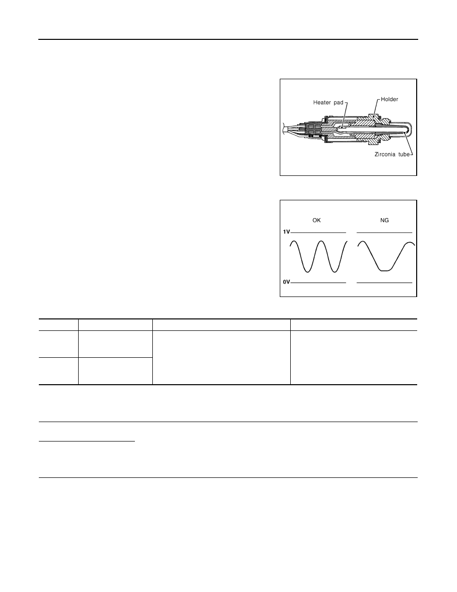
The heated oxygen sensor 2, after three way catalyst (manifold),

monitors the oxygen level in the exhaust gas on each bank.

Even if switching characteristics of the air fuel ratio (A/F) sensor 1

are shifted, the air-fuel ratio is controlled to stoichiometric, by the sig-

nal from the heated oxygen sensor 2.

This sensor is made of ceramic zirconia. The zirconia generates volt-

age from approximately 1V in richer conditions to 0V in leaner condi-

tions.

Under normal conditions the heated oxygen sensor 2 is not used for

engine control operation.

On Board Diagnosis Logic

INFOID:0000000005569195

The heated oxygen sensor 2 has a much longer switching time

between rich and lean than the air fuel ratio (A/F) sensor 1. The oxy-

gen storage capacity of the three way catalyst 1 causes the longer

switching time. To judge the malfunctions of heated oxygen sensor

2, ECM monitors whether the switching response of the sensor's

voltage is faster than specified during various driving conditions such

as fuel cut.

DTC Confirmation Procedure

INFOID:0000000005569196

1.

INSPECTION START

Do you have CONSULT-III?

YES

>> GO TO 2.

NO

>> GO TO 7.

2.

PRECONDITIONING

If DTC Confirmation Procedure has been previously conducted, always perform the following procedure

before conducting the next test.

1. Turn ignition switch OFF and wait at least 10 seconds.

2. Turn ignition switch ON.

3. Turn ignition switch OFF and wait at least 10 seconds.

TESTING CONDITION:

For better results, perform “DTC WORK SUPPORT” at a temperature of 0 to 30

°

C (32 to 86

°

F).

>> GO TO 3.

SEF327R

SEF302U

DTC No.

Trouble diagnosis name

DTC detecting condition

Possible cause

P0139

Heated oxygen sensor 2 
(bank 1) circuit slow re-
sponse

The switching time between rich and lean of a 
heated oxygen sensor 2 signal delays more 
than the specified time computed by ECM.

• Harness or connectors

(The sensor circuit is open or shorted)

• Heated oxygen sensor 2
• Fuel system
• EVAP system
• Intake air system

P0159

Heated oxygen sensor 2 
(bank 2) circuit slow re-
sponse

2010 Pathfinder

P0139, P0159 HO2S2

EC-181

< COMPONENT DIAGNOSIS >

[VQ40DE]

C

D

E

F

G

H

I

J

K

L

M

A

EC

N

P

O

3.

PERFORM DTC CONFIRMATION PROCEDURE

With CONSULT-III

1. Turn ignition switch ON and select “DATA MONITOR” mode with CONSULT-III.

2. Start engine and warm it up to the normal operating temperature.

3. Turn ignition switch OFF and wait at least 10 seconds.

4. Turn ignition switch ON.

5. Turn ignition switch OFF and wait at least 10 seconds.

6. Start engine and keep the engine speed between 3,500 and 4,000 rpm for at least 1 minute under no load.

7. Let engine idle for 1 minute.

8. Make sure that “COOLAN TEMP/S” indicates more than 70

°

C (158

°

F).

9. Drive the vehicle at a speed of 60 km/h (38 MPH) on the suitable gear position and keep the speed.

CAUTION:

Always drive vehicle at a safe speed.

10. Release the accelerator pedal fully at least 5 seconds.

CAUTION:

• Make it the condition that engine brake operates.

• Always drive vehicle safely.

• Never apply brake when releasing the accelerator pedal.

11. Repeat step 9 and 10 at least 8 times.

12. Check the following item of “DATA MONITOR”. 

Is “CMPLT” displayed on CONSULT-III screen?

YES

>> GO TO 6.

NO-1: “CMPLT” are not displayed on DIAG 1>>Perform DTC confirmation procedure again.

NO-2: “CMPLT” are not displayed on DIAG 2>>GO TO 4.

4.

PERFORM DTC WORK SUPPORT

1. Open engine hood.

2. Select “HO2S2 (B1) P0139” or “HO2S2 (B2) P0159” of “HO2S2” in “DTC WORK SUPPORT” mode with

CONSULT-III.

3. Start engine and follow the instruction of CONSULT-III display.

NOTE:

It will take at most 10 minutes until “COMPLETED” is displayed.

Is “COMPLETED” displayed on CONSULT-III screen?

YES

>> GO TO 6.

NO

>> GO TO 5.

5.

PERFORM DTC CONFIRMATION PROCEDURE AGAIN

1. Turn ignition switch OFF and leave the vehicle in a cool place (soak the vehicle).

2. Perform DTC confirmation procedure again.

>> GO TO 3.

6.

PERFORM SELF-DIAGNOSIS

With CONSULT-III

Perform ECM self-diagnosis.
Is DTC “P0139” or “P0159” detected?

YES

>> Proceed to 

EC-182, "Diagnosis Procedure"

.

NO

>> INSPECTION END

7.

PERFORM COMPONENT FUNCTION CHECK

DTC

Data monitor item

Status

P0139

HO2 S2 DIAG1 (B1)

CMPLT

HO2 S2 DIAG2 (B1)

P0159

HO2 S2 DIAG1 (B2)

HO2 S2 DIAG2 (B2)

2010 Pathfinder

EC-182

< COMPONENT DIAGNOSIS >

[VQ40DE]

P0139, P0159 HO2S2

Perform component function check. Refer to 

EC-182, "Overall Function Check"

.

NOTE:

Use component function check to check the overall function of the heated oxygen sensor 2 circuit. During this

check, a 1st trip DTC might not be confirmed.
Is the inspection result normal?

YES

>> INSPECTION END

NO

>> Proceed to  

EC-182, "Diagnosis Procedure"

.

Overall Function Check

INFOID:0000000005257164

Use this procedure to check the overall function of the heated oxygen sensor 2 circuit. During this check, a 1st

trip DTC might not be confirmed.

 WITH GST

1. Start engine and warm it up to the normal operating temperature.
2. Turn ignition switch OFF and wait at least 10 seconds.
3. Turn ignition switch ON.
4. Turn ignition switch OFF and wait at least 10 seconds.
5. Start engine and keep the engine speed between 3,500 and 4,000 rpm for at least 1 minute under no load.
6. Let engine idle for 1 minute.
7. Set voltmeter probes between ECM terminal 74 [HO2S2 (B1) signal] or 55 [HO2S2 (B2) signal] and

ground.

8. Check the voltage when revving up to 4,000 rpm under no load

at least 10 times.

(Depress and release accelerator pedal as soon as possible.)

A change of voltage should be more than 0.8 V for 1 second

during this procedure.

If the voltage can be confirmed in step 6, step 7 is not nec-

essary.

9. Keep vehicle at idling for 10 minutes, then check the voltage. Or

check the voltage when coasting from 80 km/h (50 MPH) in D

position with “OD” OFF.

A change of voltage should be more than 0.8 V for 1 second

during this procedure.

10. If NG, go to 

EC-182, "Diagnosis Procedure"

.

Diagnosis Procedure

INFOID:0000000005257165

1.

CHECK GROUND CONNECTIONS

1. Turn ignition switch OFF.

2. Loosen and retighten three ground screws on the body. Refer to 

EC-100, "Ground Inspection"

.

OK or NG

OK

>> GO TO 2.

NG

>> Repair or replace ground connections.

2.

CLEAR THE SELF-LEARNING DATA


With CONSULT-III

PBIB1607E

BBIA0539E

2010 Pathfinder

P0139, P0159 HO2S2

EC-183

< COMPONENT DIAGNOSIS >

[VQ40DE]

C

D

E

F

G

H

I

J

K

L

M

A

EC

N

P

O

1. Start engine and warm it up to normal operating temperature.

2. Select “SELF-LEARNING CONT” in “WORK SUPPORT” mode with CONSULT-III.

3. Clear the self-learning control coefficient by touching “CLEAR”.

4. Run engine for at least 10 minutes at idle speed.

Is the 1st trip DTC P0171, P0172, P0174 or P0175 detected?

Is it difficult to start engine?


Without CONSULT-III

1. Start engine and warm it up to normal operating temperature.

2. Turn ignition switch OFF.

3. Disconnect mass air flow sensor harness connector, and restart

and run engine for at least 5 seconds at idle speed.

4. Stop engine and reconnect mass air flow sensor harness con-

nector.

5. Make sure DTC P0102 is displayed.

6. Erase the DTC memory. Refer to 

EC-53, "Emission-related

Diagnostic Information"

.

7. Make sure DTC P0000 is displayed.

8. Run engine for at least 10 minutes at idle speed.

Is the 1st trip DTC P0171, P0172, P0174 or P0175 detected?

Is it difficult to start engine?

Yes or No

Yes

>> Perform trouble diagnosis for DTC P0171, P0174 or P0172, P0175. Refer to 

EC-186, "On Board

Diagnosis Logic"

 or 

EC-192, "On Board Diagnosis Logic"

.

No

>> GO TO 3.

3.

CHECK HO2S2 GROUND CIRCUIT FOR OPEN AND SHORT

1. Turn ignition switch OFF.

2. Disconnect heated oxygen sensor 2 harness connector.

3. Disconnect ECM harness connector.

4. Check harness continuity between HO2S2 terminal 4 and ECM terminal 78.

Refer to Wiring Diagram.

BBIA0541E

Continuity should exist.

BBIA0540E

2010 Pathfinder

EC-184

< COMPONENT DIAGNOSIS >

[VQ40DE]

P0139, P0159 HO2S2

5. Also check harness for short to ground and short to power.
OK or NG

OK

>> GO TO 4.

NG

>> Repair open circuit or short to ground or short to power in harness or connectors.

4.

CHECK HO2S2 INPUT SIGNAL CIRCUIT FOR OPEN AND SHORT

1. Check harness continuity between ECM terminal and HO2S2 terminal as follows.

Refer to Wiring Diagram.

2. Check harness continuity between the following terminals and ground.

Refer to Wiring Diagram.

3. Also check harness for short to power.
OK or NG

OK

>> GO TO 5.

NG

>> Repair open circuit or short to ground or short to power in harness or connectors.

5.

CHECK HEATED OXYGEN SENSOR 2

Refer to 

EC-184, "Component Inspection"

.

OK or NG

OK

>> GO TO 6.

NG

>> Replace malfunctioning heated oxygen sensor 2.

6.

CHECK INTERMITTENT INCIDENT

Refer to 

GI-33, "Work Flow"

.

>>

INSPECTION END

Component Inspection

INFOID:0000000005257166

HEATED OXYGEN SENSOR 2

 With CONSULT-III

1. Turn ignition switch ON and select “DATA MONITOR” mode with CONSULT-III.
2. Start engine and warm it up to the normal operating temperature.
3. Turn ignition switch OFF and wait at least 10 seconds.
4. Start engine and keep the engine speed between 3,500 and 4,000 rpm for at least 1 minute under no load.
5. Let engine idle for 1 minute.
6. Select “FUEL INJECTION” in “ACTIVE TEST” mode, and select “HO2S2 (B1)/(B2)” as the monitor item

with CONSULT-III.

DTC

Terminals

Bank

ECM

Sensor

P0139

74

1

1

P0159

55

1

2

Continuity should exist.

DTC

Terminals

Bank

ECM

Sensor

P0139

74

1

1

P0159

55

1

2

Continuity should not exist.

2010 Pathfinder

P0139, P0159 HO2S2

EC-185

< COMPONENT DIAGNOSIS >

[VQ40DE]

C

D

E

F

G

H

I

J

K

L

M

A

EC

N

P

O

7. Check “HO2S2 (B1)/(B2)” at idle speed when adjusting “FUEL INJECTION” to 

±

25%.

“HO2S2 (B1)/(B2)” should be above 0.68V at least once when the “FUEL INJECTION” is +25%.

“HO2S2 (B1)/(B2)” should be below 0.18V at least once when the “FUEL INJECTION” is 

25%.

CAUTION:

• Discard any heated oxygen sensor which has been dropped from a height of more than 0.5 m (19.7

in) onto a hard surface such as a concrete floor; use a new one.

• Before installing new oxygen sensor, clean exhaust system threads using Oxygen Sensor Thread

Cleaner tool J-43897-18 or J-43897-12 and approved anti-seize lubricant.

 Without CONSULT-III

1. Start engine and warm it up to the normal operating temperature.
2. Turn ignition switch OFF and wait at least 10 seconds.
3. Start engine and keep the engine speed between 3,500 and 4,000 rpm for at least 1 minute under no load.
4. Let engine idle for 1 minute.
5. Set voltmeter probes between ECM terminal 74 [HO2S2 (B1) signal] or 55 [HO2S2 (B2) signal] and

ground.

6. Check the voltage when revving up to 4,000 rpm under no load

at least 10 times.

(Depress and release accelerator pedal as soon as possible.)

The voltage should be above 0.68V and below 0.18V at least

once during this procedure.

If the voltage can be confirmed at step 6, step 7 is not nec-

essary.

7. Keep vehicle at idling for 10 minutes, then check voltage. Or

check the voltage when coasting from 80 km/h (50 MPH) in D

position with “OD” OFF.

The voltage should be above 0.68V and below 0.18V at least

once during this procedure.

8. If NG, replace heated oxygen sensor 2.

CAUTION:

• Discard any heated oxygen sensor which has been dropped from a height of more than 0.5 m (19.7

in) onto a hard surface such as a concrete floor; use a new one.

• Before installing new oxygen sensor, clean exhaust system threads using Oxygen Sensor Thread

Cleaner tool J-43897-18 or J-43897-12 and approved anti-seize lubricant.

PBIB3458E

PBIB1607E

2010 Pathfinder

EC-186

< COMPONENT DIAGNOSIS >

[VQ40DE]

P0171, P0174 FUEL INJECTION SYSTEM FUNCTION

P0171, P0174 FUEL INJECTION SYSTEM FUNCTION

On Board Diagnosis Logic

INFOID:0000000005257167

With the Air-Fuel Mixture Ratio Self-Learning Control, the actual mixture ratio can be brought closely to the

theoretical mixture ratio based on the mixture ratio feedback signal from the air fuel ratio (A/F) sensor 1. The

ECM calculates the necessary compensation to correct the offset between the actual and the theoretical

ratios.

In case the amount of the compensation value is extremely large (the actual mixture ratio is too lean), the

ECM judges the condition as the fuel injection system malfunction and illuminates the MIL (2 trip detection

logic).

DTC Confirmation Procedure

INFOID:0000000005550527

NOTE:

If DTC Confirmation Procedure has been previously conducted, always turn ignition switch OFF and wait at

least 10 seconds before conducting the next test.

 WITH CONSULT-III

1. Start engine and warm it up to normal operating temperature.
2. Turn ignition switch OFF and wait at least 10 seconds.
3. Turn ignition switch ON and select “SELF-LEARNING CONT” in “WORK SUPPORT” mode with CON-

SULT-III.

4. Clear the self-learning control coefficient by touching “CLEAR”.
5. Start engine.

If it is difficult to start engine, the fuel injection system has a malfunction.

Performing the following procedure is advised.

a. Crank engine while depressing accelerator pedal.

NOTE:

When depressing accelerator pedal three-fourths (3/4) or more, the control system does not start the

engine. Do not depress accelerator pedal too much.

b. If engine starts, go to 

EC-187, "Diagnosis Procedure"

.

If engine does not start, check exhaust and intake air leakage visually.

6. Keep engine at idle for at least 5 minutes.
7. Check 1st trip DTC.
8. The 1st trip DTC P0171 or P0174 should be detected at this stage, if a malfunction exists. If so, go to 

EC-

187, "Diagnosis Procedure"

.

NOTE:

If 1st trip DTC is not detected during above procedure, performing the following procedure is advised.

a. Turn ignition switch OFF and wait at least 10 seconds.
b. Start engine.
c.

Maintain the following conditions for at least 10 consecutive minutes.

Sensor

Input signal to ECM

ECM function

Actuator

A/F sensor 1

Density of oxygen in exhaust gas
(Mixture ratio feedback signal)

Fuel injection 
control

Fuel injector

DTC No.

Trouble diagnosis 

name

DTC detecting condition

Possible cause

P0171
0171
(Bank 1)

Fuel injection system 
too lean

• Fuel injection system does not operate properly.
• The amount of mixture ratio compensation is too 

large. (The mixture ratio is too lean.)

• Intake air leaks
• Air fuel ratio (A/F) sensor 1
• Fuel injector
• Exhaust gas leaks
• Incorrect fuel pressure
• Lack of fuel
• Mass air flow sensor
• Incorrect PCV hose connection

P0174
0174
(Bank 2)

2010 Pathfinder

P0171, P0174 FUEL INJECTION SYSTEM FUNCTION

EC-187

< COMPONENT DIAGNOSIS >

[VQ40DE]

C

D

E

F

G

H

I

J

K

L

M

A

EC

N

P

O

Hold the accelerator pedal as steady as possible.

CAUTION:

Always drive vehicle at a safe speed.

d. Check 1st trip DTC.
e. If 1st trip DTC is detected, go to 

EC-187, "Diagnosis Procedure"

.

 WITH GST

1. Start engine and warm it up to normal operating temperature.
2. Turn ignition switch OFF and wait at least 10 seconds.
3. Disconnect mass air flow sensor harness connector.
4. Restart engine and let it idle for at least 5 seconds.
5. Stop engine and reconnect mass air flow sensor harness con-

nector.

6. Select Service $03 with GST. Check that DTC P0102 is

detected.

7. Select Service $04 with GST and erase the DTC P0102.
8. Start engine.

If it is difficult to start engine, the fuel injection system has a mal-

function.

Performing the following procedure is advised.

a. Crank engine while depressing accelerator pedal.

NOTE:

When depressing accelerator pedal three-fourths (3/4) or more, the control system does not start the

engine. Do not depress accelerator pedal too much.

b. If engine starts, go to 

EC-187, "Diagnosis Procedure"

If engine does not start, check exhaust and intake air leakage visually.

9. Keep engine at idle for at least 5 minutes.
10. Check 1st trip DTC.
11. The 1st trip DTC P0171 or P0174 should be detected at this stage, if a malfunction exists. If so, go to 

EC-

187, "Diagnosis Procedure"

.

NOTE:

If 1st trip DTC is not detected during above procedure, performing the following procedure is advised.

a. Turn ignition switch OFF and wait at least 10 seconds.
b. Start engine.
c. Maintain the following conditions for at least 10 consecutive minutes.

Hold the accelerator pedal as steady as possible.

CAUTION:

Always drive vehicle at a safe speed.

d. Check 1st trip DTC.
e. If 1st trip DTC is detected, go to 

EC-187, "Diagnosis Procedure"

.

Diagnosis Procedure

INFOID:0000000005257169

1.

CHECK EXHAUST GAS LEAK

1. Start engine and run it at idle.

VHCL SPEED SE

50 - 120 km/h (31 - 75 MPH)

VHCL SPEED SE

50 - 120 km/h (31 - 75 MPH)

BBIA0541E

2010 Pathfinder


Content      ..     259      260      261      262     ..