Nissan Pathfinder (2010 year). Manual - part 255
EC-132
< COMPONENT DIAGNOSIS >
[VQ40DE]
P0116 ECT SENSOR
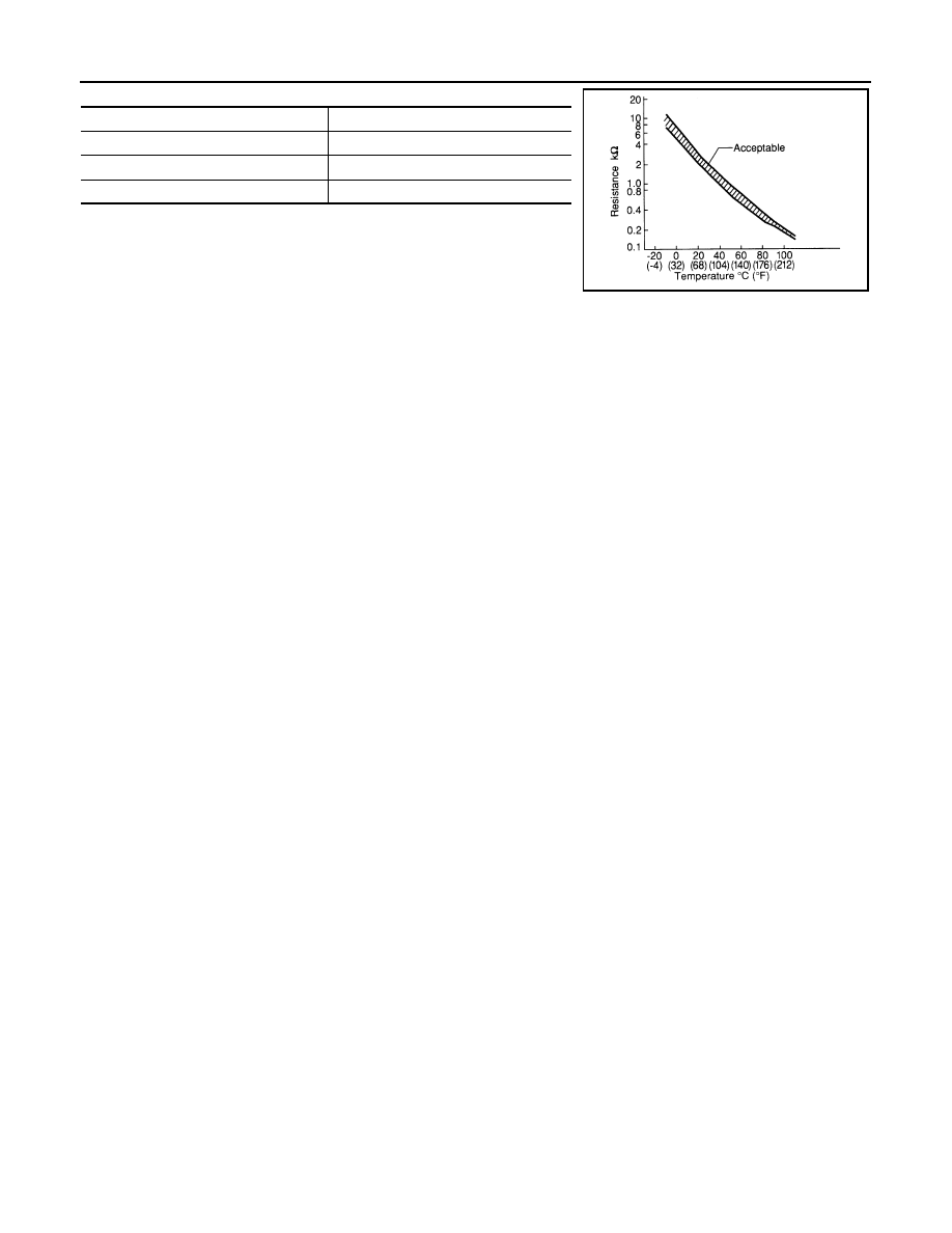
2. If NG, replace engine coolant temperature sensor.
Engine coolant temperature
°
C (
°
F)]
Resistance (k
Ω
20 (68)
2.1 - 2.9
50 (122)
0.68 - 1.00
90 (194)
0.236 - 0.260
SEF012P
2010 Pathfinder