Nissan Pathfinder (2010 year). Manual - part 252
EC-108
< COMPONENT DIAGNOSIS >
[VQ40DE]
P0031, P0032, P0051, P0052 A/F SENSOR 1 HEATER
OK or NG
OK
>> GO TO 5.
NG
>> Repair open circuit or short to ground or short to power in harness or connectors.
5.
CHECK AIR FUEL RATIO (A/F) SENSOR 1 HEATER
EC-108, "Component Inspection"
OK or NG
OK
>> GO TO 6.
NG
>> GO TO 7.
6.
CHECK INTERMITTENT INCIDENT
Perform
GI-37, "Intermittent Incident"
.
OK or NG
OK
>> GO TO 7.
NG
>> Repair or replace.
7.
REPLACE AIR FUEL RATIO (A/F) SENSOR 1
Replace malfunctioning air fuel ratio (A/F) sensor 1.
CAUTION:
• Discard any air fuel ratio (A/F) sensor which has been dropped from a height of more than 0.5 m
(19.7 in) onto a hard surface such as a concrete floor; use a new one.
• Before installing new air fuel ratio (A/F) sensor, clean exhaust system threads using Heated Oxygen
Sensor Thread Cleaner tool J-43897-18 or J-43897-12 and approved anti-seize lubricant.
>>
INSPECTION END
Component Inspection
INFOID:0000000005257076
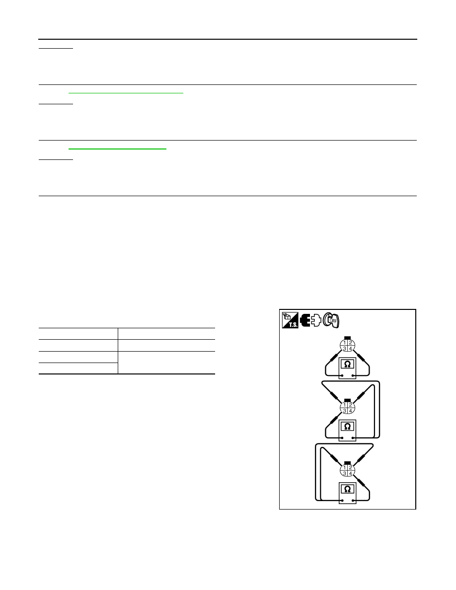
AIR FUEL RATIO (A/F) SENSOR 1 HEATER
1. Check resistance between A/F sensor 1 terminals as follows.
2. If NG, replace air fuel ratio (A/F) sensor 1.
CAUTION:
• Discard any A/F sensor which has been dropped from a
height of more than 0.5 m (19.7 in) onto a hard surface such
as a concrete floor; use a new one.
• Before installing new A/F sensor, clean exhaust system
threads using Heated Oxygen Sensor Thread Cleaner tool J-
43897-18 or J-43897-12 and approved anti-seize lubricant.
Terminal No.
Resistance
3 and 4
1.80 - 2.44
Ω
[at 25
°
C (77
°
F)]
3 and 1, 2
∞
Ω
(Continuity should not exist)
4 and 1, 2
PBIB3309E
2010 Pathfinder