Nissan Pathfinder (2010 year). Manual - part 244


  Index      Manuals     Nissan Pathfinder (2010 year) - Service and Repair Manual


Search            copyright infringement  


Content      ..     242      243      244      245     ..


Nissan Pathfinder (2010 year). Manual - part 244


EC-44

< FUNCTION DIAGNOSIS >

[VQ40DE]

COOLING FAN CONTROL

COOLING FAN CONTROL

Description

INFOID:0000000005257042

SYSTEM DESCRIPTION

Cooling Fan Control

*1: The ECM determines the start signal status by the signals of engine speed and battery voltage.
*2: This signal is sent to ECM via the CAN communication line.

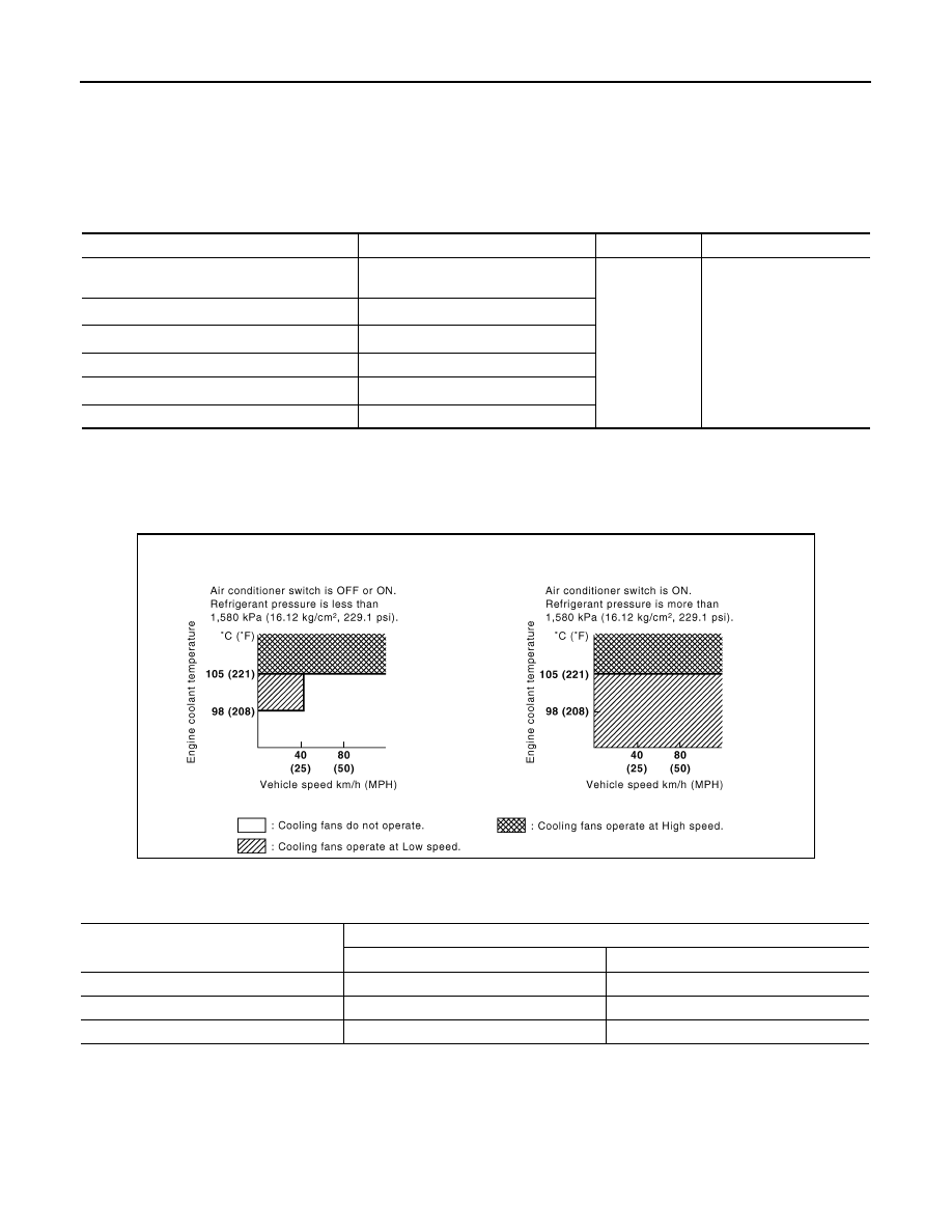
The ECM controls the cooling fan corresponding to the vehicle speed, engine coolant temperature, refrigerant

pressure, and air conditioner ON signal. The control system has 3-step control [HIGH/LOW/OFF].

Cooling Fan Operation

Cooling Fan Relay Operation

The ECM controls cooling fan relays in the IPDM E/R via the CAN communication line.

Sensor

Input Signal to ECM

ECM function

Actuator

Crankshaft position sensor (POS)
Camshaft position sensor (PHASE)

Engine speed*

1

Cooling fan 
control

IPDM E/R
(Cooling fan relays)

Battery

Battery voltage*

1

Wheel sensor

Vehicle speed*

2

Engine coolant temperature sensor

Engine coolant temperature

Air conditioner switch

Air conditioner ON signal*

2

Refrigerant pressure sensor

Refrigerant pressure

PBIB2531E

Cooling fan speed

Cooling fan relay

LO

HI

Stop (OFF)

OFF

OFF

Low (LOW)

ON

OFF

High (HI)

ON

ON

2010 Pathfinder

EVAPORATIVE EMISSION SYSTEM

EC-45

< FUNCTION DIAGNOSIS >

[VQ40DE]

C

D

E

F

G

H

I

J

K

L

M

A

EC

N

P

O

EVAPORATIVE EMISSION SYSTEM

Description

INFOID:0000000005257043

SYSTEM DESCRIPTION

The evaporative emission system is used to reduce hydrocarbons emitted into the atmosphere from the fuel

system. This reduction of hydrocarbons is accomplished by activated charcoals in the EVAP canister.

The fuel vapor in the sealed fuel tank is led into the EVAP canister which contains activated carbon and the

vapor is stored there when the engine is not operating or when refueling to the fuel tank.

The vapor in the EVAP canister is purged by the air through the purge line to the intake manifold when the

engine is operating. EVAP canister purge volume control solenoid valve is controlled by ECM. When the

engine operates, the flow rate of vapor controlled by EVAP canister purge volume control solenoid valve is

proportionally regulated as the air flow increases.

EVAP canister purge volume control solenoid valve also shuts off the vapor purge line during decelerating.

PBIB3639E

2010 Pathfinder

EC-46

< FUNCTION DIAGNOSIS >

[VQ40DE]

EVAPORATIVE EMISSION SYSTEM

EVAPORATIVE EMISSION LINE DRAWING

PBIB2528E

2010 Pathfinder

EVAPORATIVE EMISSION SYSTEM

EC-47

< FUNCTION DIAGNOSIS >

[VQ40DE]

C

D

E

F

G

H

I

J

K

L

M

A

EC

N

P

O

1.

EVAP vapor purge line

2.

EVAP control system pressure sen-
sor

3.

EVAP canister vent control valve

4.

EVAP canister

5.

Drain filter

6.

Fuel filler pipe

:Vehicle front

:Previous page

ALBIA0366ZZ

2010 Pathfinder

EC-48

< FUNCTION DIAGNOSIS >

[VQ40DE]

INTAKE VALVE TIMING CONTROL

INTAKE VALVE TIMING CONTROL

Description

INFOID:0000000005257044

SYSTEM DESCRIPTION

*: This signal is sent to the ECM via the CAN communication line

This mechanism hydraulically controls cam phases continuously with the fixed operating angle of the intake

valve.

The ECM receives signals such as crankshaft position, camshaft position, engine speed, and engine coolant

temperature. Then, the ECM sends ON/OFF pulse duty signals to the intake valve timing control solenoid

valve depending on driving status. This makes it possible to control the shut/open timing of the intake valve to

increase engine torque in low/mid speed range and output in high-speed range.

Sensor

Input signal to ECM

ECM function

Actuator

Crankshaft position sensor (POS)

Engine speed and piston position

Intake valve 
timing control

Intake valve timing control 
solenoid valve

Camshaft position sensor (PHASE)

Engine coolant temperature sensor

Engine coolant temperature

Wheel sensor

Vehicle speed*

PBIB3279E

2010 Pathfinder

VARIABLE INDUCTION AIR SYSTEM

EC-49

< FUNCTION DIAGNOSIS >

[VQ40DE]

C

D

E

F

G

H

I

J

K

L

M

A

EC

N

P

O

VARIABLE INDUCTION AIR SYSTEM

Description

INFOID:0000000005257045

SYSTEM DESCRIPTION

*: ECM determines the start signal status by the signals of engine speed and battery voltage.

When the engine is running at medium speed, the ECM sends the ON signal to the VIAS control solenoid

valve. This signal introduces the intake manifold vacuum into the power valve actuator and therefore closes

the power valve.

Under this condition, the effective intake manifold length is equivalent to the total length of passage A and pas-

sage B. This long intake manifold provides increased amount of intake air, which results in improved suction

efficiency and higher torque.

When engine is running at low or high speed, the ECM sends the OFF signal to the VIAS control solenoid

valve and the power valve is opened.

Under this condition, the effective intake manifold length is equivalent to the length of passage B. This short-

ened intake manifold length results in enhanced engine output due to reduced suction resistance under high

speeds.

COMPONENT DESCRIPTION

Power Valve

Sensor

Input Signal to ECM

ECM function

Actuator

Crankshaft position sensor (POS)
Camshaft position sensor (PHASE)

Engine speed*

VIAS control

VIAS control solenoid valve

Mass air flow sensor

Amount of intake air

Engine coolant temperature sensor

Engine coolant temperature

Throttle position sensor

Throttle position

Accelerator pedal position sensor

Accelerator pedal position

Battery

Battery voltage*

PBIB1822E

2010 Pathfinder

EC-50

< FUNCTION DIAGNOSIS >

[VQ40DE]

VARIABLE INDUCTION AIR SYSTEM

The power valve is installed in intake manifold collector and used to

control the suction passage of the variable induction air control sys-

tem. It is set in the fully closed or fully opened position by the power

valve actuator operated by the vacuum stored in the surge tank. The

vacuum in the surge tank is controlled by the VIAS control solenoid

valve.

VIAS Control Solenoid Valve

The VIAS control solenoid valve cuts the intake manifold vacuum

signal for power valve control. It responds to ON/OFF signals from

the ECM. When the solenoid is off, the vacuum signal from the

intake manifold is cut. When the ECM sends an ON signal the coil

pulls the plunger downward and feeds the vacuum signal to the

power valve actuator.

BBIA0569E

BBIA0569E

2010 Pathfinder

VARIABLE INDUCTION AIR SYSTEM

EC-51

< FUNCTION DIAGNOSIS >

[VQ40DE]

C

D

E

F

G

H

I

J

K

L

M

A

EC

N

P

O

Vacuum Hose Drawing

INFOID:0000000005257046

Refer to 

EC-28, "System Diagram"

 for Vacuum Control System.

PBIB2529E

2010 Pathfinder


Content      ..     242      243      244      245     ..