Nissan Pathfinder (2010 year). Manual - part 228


  Index      Manuals     Nissan Pathfinder (2010 year) - Service and Repair Manual


Search            copyright infringement  


Content      ..     226      227      228      229     ..


Nissan Pathfinder (2010 year). Manual - part 228


FRONT FINAL DRIVE

DLN-397

< DISASSEMBLY AND ASSEMBLY >

[FRONT FINAL DRIVE: M205]

C

E

F

G

H

I

J

K

L

M

A

B

DLN

N

O

P

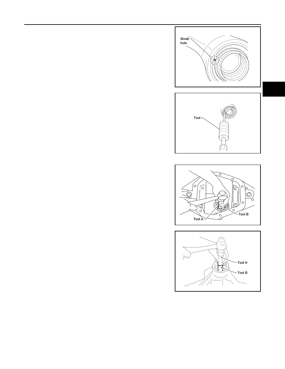
7. Place a small hole in the front oil seal case using suitable tool.

8. Remove the front oil seal using Tool as shown.

9. Remove the drive pinion front bearing inner race.
10. Remove the drive pinion front bearing outer race using Tool as

shown. Locate the driver on the back edge of the drive pinion

front bearing outer race, then drive the drive pinion front bearing

outer race out.

CAUTION:

Do not damage gear carrier.

11. Remove the drive pinion rear bearing outer race using Tool as

shown. Locate the driver on the back edge of the drive pinion

rear bearing outer race, then drive the drive pinion rear bearing

outer race out.

CAUTION:

Do not damage gear carrier.

INSPECTION AFTER DISASSEMBLY

Clean the disassembled parts. Then inspect the parts for wear or damage. If wear or damage are found, follow

the measures below.

Drive Pinion and Drive Gear

• If the drive pinion and drive gear teeth do not mesh or line-up correctly, determine the cause and adjust,

repair, or replace as necessary.

• If the drive pinion or drive gear are worn, cracked, damaged, pitted or chipped (by friction) noticeably,

replace with new drive pinion and drive gear.

LDIA0129E

Tool number

:  —

SP8P

LDIA0130E

Tool number

A:  —

C-4171

B: —

D-103

LDIA0131E

Tool number

A:  —

C-4171

B: —

C-4307

LDIA0132E

2010 Pathfinder

DLN-398

< DISASSEMBLY AND ASSEMBLY >

[FRONT FINAL DRIVE: M205]

FRONT FINAL DRIVE

• Drive pinion and drive gear are supplied in matched sets only. Matching numbers on both drive pinion and

drive gear are etched for verification. If a new drive pinion and drive gear set are being used, verify the num-

bers of each drive pinion and drive gear before proceeding with assembly.

Bearing

• If bearings are chipped (by friction), pitted, worn, rusted, scratched, or unusual noise is coming from bearing,

replace with new bearing assembly (as a new set).

• Bearing must be replaced with a new one whenever disassembled.

Side Gear and Pinion Mate Gear

• If any cracks or damage are found on the surface of the teeth, replace with new one.

• If any worn or chipped marks are found on the side of the side gear and pinion mate gear which contact the

thrust washer, replace with new one.

• Replace both side gear and pinion mate gear as a set when replacing side gear or pinion mate gear.

Side Gear Thrust Washer and Pinion Mate Thrust Washer

• If any chips (by friction), damage, or unusual wear are found, replace with new one.

Gear Carrier

• If any wear or cracks are found on the contact sides of gear carrier, replace with new one.

Companion Flange

• If any chips (about 0.1mm, 0.004 in) or other damage on the companion flange surface which contacts the

front oil seal lips are found, replace with new one.

ADJUSTING AND SELECTING WASHERS

Side Gear Back Clearance

• Assemble the differential parts if they are disassembled. Refer to 

DLN-389, "Exploded View"

1. Place the differential case straight up so that the side gear to be

measured is upward.

PDIA0460E

2010 Pathfinder

FRONT FINAL DRIVE

DLN-399

< DISASSEMBLY AND ASSEMBLY >

[FRONT FINAL DRIVE: M205]

C

E

F

G

H

I

J

K

L

M

A

B

DLN

N

O

P

2. Using feeler gauges, measure the clearance between the side

gear back and differential case at three different points, while

rotating the side gear. Average the three readings to calculate

the clearance. (Measure the clearance of the other side as well.)

• If the side gear back clearance is outside of the specification,

use a thicker or thinner side gear thrust washer to adjust.

Refer to 

DLN-406, "Inspection and Adjustment"

.

CAUTION:

• Insert feeler gauges with the same thickness on both

sides to prevent side gear from tilting.

• Each gear should rotate smoothly without excessive

resistance during differential motion.

• Select a side gear thrust washer for right and left individually.

NOTE:

Side gear back clearance is clearance between side gear and differential case for adjusting side gear

backlash.

Drive Pinion Height

• Drive gear and drive pinion are supplied in matched sets only.

Matching numbers on both drive pinion and drive gear are etched

for verification. If a new gear set is being used, verify the numbers

of each drive pinion and drive gear before proceeding with assem-

bly.

• The mounting distance from the centerline of the drive gear to the back face of the drive pinion for the M205

final drive assembly is 103.5 mm (4.0748 inches).

On the button end of each drive pinion, there is etched a plus (+) number, a minus (-) number, or a zero (0),

which indicates the best running position for each particular gear set. This dimension is controlled by a

selective drive pinion height adjusting washer between the drive pinion rear bearing inner race and drive pin-

ion.

For example: If a drive pinion is etched m+8 (+3), it would require 0.08 mm (0.003 inch) less drive pinion

height adjusting washer than a drive pinion etched “0”. This means decreasing drive pinion height adjusting

washer thickness; increases the mounting distance of the drive pinion to 103.6 mm (4.0778 inches). If a

drive pinion is etched m-8 (-3), it would require adding 0.08mm (0.003 inch) more to the drive pinion height

adjusting washer than would be required if the drive pinion were etched “0”. By adding 0.08 mm (0.003 inch),

the mounting distance of the drive pinion was decreased to 103.4 mm (4.0718 inches) which is just what a

m-8 (-3) etching indicated.      

• To change the drive pinion height, use different drive pinion height adjusting washers which come in different

thickness.

• Use the following tables as a guide for selecting the correct drive pinion height adjusting washer thickness to

add or subtract from the old drive pinion height adjusting washer.

Side gear back 
clearance:

Refer to 

DLN-406, "Inspec-

tion and Adjustment"

If the side gear back clearance is greater than 
specification:

Use a thicker side gear thrust washer.

If the side gear back clearance is less than spec-
ification:

Use a thinner side gear thrust washer.

PDIA0576E

SDIA2241E

2010 Pathfinder

DLN-400

< DISASSEMBLY AND ASSEMBLY >

[FRONT FINAL DRIVE: M205]

FRONT FINAL DRIVE

ASSEMBLY

Drive Pinion Assembly

1. Install drive pinion rear bearing outer race using Tools.

2. Install drive pinion front bearing outer race using Tools.

3. Select drive pinion height adjusting washer. Refer to 

DLN-406, "Inspection and Adjustment"

.

OLD DRIVE 

PINION 

MARKING

NEW DRIVE PINION MARKING mm (in)

-10 (-4)

-8 (-3)

-5 (-2)

-3 (-1)

0 (0)

+3 (+1)

+5 (+2)

+8 (+3)

+10 (+4)

+10 (+4)

+0.20

(+0.008)

+0.18

(+0.007) 

+0.15

(+0.006)

+0.13

(+0.005)

+0.10

(+0.004)

+0.08

(+0.003)

+0.05

(+0.002)

+0.02

(+0.001)

0

(0)

+8 (+3)

+0.18

(+0.007)

+0.15

(+0.006)

+0.13

(+0.005)

+0.10

(+0.004)

+0.08

(+0.003)

+0.05

(+0.002)

+0.02

(+0.001)

0

(0)

-0.02

(-0.001)

+5 (+2)

+0.15

(+0.006)

+0.13

(+0.005)

+0.10

(+0.004)

+0.08

(+0.003)

+0.05

(+0.002)

+0.02

(+0.001)

0

(0)

-0.02

(-0.001)

-0.05

(-0.002)

+3 (+1)

+0.13

(+0.005)

+0.10

(+0.004)

+0.08

(+0.003)

+0.05

(+0.002)

+0.02

(+0.001)

0

(0)

-0.02

(-0.001)

-0.05

(-0.002)

-0.08

(-0.003)

0 (0)

+0.10

(+0.004)

+0.08

(+0.003)

+0.05

(+0.002)

+0.02 

(+0.001)

0

(0)

-0.02

(-0.001)

-0.05

(-0.002)

-0.08

(-0.003)

-0.10

(-0.004)

-3 (-1)

+0.08

(+0.003)

+0.05

(+0.002)

+0.02

(+0.001)

0

(0)

-0.02

(-0.001)

-0.05

(-0.002)

-0.08

(-0.003)

-0.10

(-0.004)

-0.13

(-0.005)

-5 (-2)

+0.05

(+0.002)

+0.02

(+0.001)

0

(0)

-0.02

(-0.001)

-0.05

(-0.002)

-0.08

(-0.003)

-0.10

(-0.004)

-0.13

(-0.005)

-0.15

(-0.006)

-8 (-3)

+0.02

(+0.001)

0

(0)

-0.02

(-0.001)

-0.05

(-0.002)

-0.08

(-0.003)

-0.10

(-0.004)

-0.13

(-0.005)

-0.15

(-0.006)

-0.18

(-0.007)

-10 (-4)

0

(0)

-0.02

(-0.001)

-0.05

(-0.002)

-0.08

(-0.003)

-0.10

(-0.004)

-0.13

(-0.005)

-0.15

(-0.006)

-0.18

(-0.007)

-0.20

(-0.008)

Tool number 

A: ST30901000 ( — )
B: KV40105230 ( — )

SDIA2251E

Tool number

A: ST35271000 ( — )
B: KV40104810 ( — )

SDIA2252E

2010 Pathfinder

FRONT FINAL DRIVE

DLN-401

< DISASSEMBLY AND ASSEMBLY >

[FRONT FINAL DRIVE: M205]

C

E

F

G

H

I

J

K

L

M

A

B

DLN

N

O

P

4. Install the selected drive pinion height adjusting washer to the

drive pinion. Press the drive pinion rear bearing inner race to it

using Tool.

CAUTION:

Do not reuse drive pinion rear bearing inner race.

5. Install the collapsible spacer to the drive pinion.

CAUTION:

Do not reuse collapsible spacer.

6. Apply differential gear oil to the drive pinion rear bearing, and

install the drive pinion assembly to the gear carrier.

7. Apply differential gear oil to the drive pinion front bearing, and

install the drive pinion front bearing inner race to the drive pinion

assembly.

CAUTION:

Do not reuse drive pinion front bearing inner race.

8. Apply multi-purpose grease to the lips of the new front oil seal.

Then drive the new front oil seal in evenly using Tools.

CAUTION:

• Do not reuse front oil seal.

• Do not incline the new front oil seal when installing.

• Apply multi-purpose grease to the lips of the new front oil

seal.

9. Install the companion flange to the drive pinion while aligning the

matching marks. Tap the companion flange until fully seated

using suitable tool.

Tool number

:  — C-4040

SDIA2253E

PDIA0708E

Tool number

A: KV38100500 (J-25273)
B: KV38102200 ( — )

PDIA0717E

SDIA2266E

2010 Pathfinder

DLN-402

< DISASSEMBLY AND ASSEMBLY >

[FRONT FINAL DRIVE: M205]

FRONT FINAL DRIVE

10. Apply anti-corrosive oil to the threads of the drive pinion and the

seating surface of the new drive pinion lock nut. Then adjust the

drive pinion lock nut tightening torque using suitable tool A, and

check the drive pinion bearing preload torque using Tool B.

CAUTION:

• Do not reuse drive pinion lock nut.

• Apply anti-corrosive oil to the threads of the drive pinion

and the seating surface of the new drive pinion lock nut.

• Adjust the drive pinion lock nut tightening torque to the

lower limit first. Do not exceed the drive pinion lock nut

specified torque. Refer to 

DLN-389, "Exploded View"

.

• If the drive pinion bearing preload torque exceeds the

specified value, replace collapsible spacer and tighten it

again to adjust. Do not loosen drive pinion lock nut to

adjust the drive pinion bearing preload torque.

• After adjustment, rotate drive pinion back and forth 2 to 3

times to check for unusual noise, rotation malfunction,

and other malfunctions.

11. Check companion flange runout. Refer to 

DLN-406, "Inspection and Adjustment"

.

12. Install the differential case assembly. Refer to 

DLN-389, "Exploded View"

.

Differential Assembly

1. Install side gear thrust washers with the same thickness as the

ones installed prior to disassembly, or reinstall the old ones on

the side gears.

2. Install the side gears and side gear thrust washers into the dif-

ferential case.

3. Install the pinion mate thrust washers to the two pinion mate

gears. Then install the pinion mate gears with the pinion mate

thrust washers by aligning them in diagonally opposite positions

and rotating them into the differential case.

Tool number

B: ST3127S000 (J-25765-A)

Drive pinion bearing pre-
load torque

Refer to 

DLN-406, "Inspec-

tion and Adjustment"

WDIA0382E

SDIA0193J

SDIA2025E

2010 Pathfinder

FRONT FINAL DRIVE

DLN-403

< DISASSEMBLY AND ASSEMBLY >

[FRONT FINAL DRIVE: M205]

C

E

F

G

H

I

J

K

L

M

A

B

DLN

N

O

P

4. Install the pinion mate shaft and align the lock pin hole on the

pinion mate shaft with the lock pin hole on the differential case.

5. Measure the side gear end play. If necessary, select the appro-

priate side gear thrust washers. Refer to 

DLN-406, "Inspection

and Adjustment"

.

6. Drive a new lock pin into the pinion mate shaft until it is flush

with the differential case using suitable tool.

CAUTION:

Do not reuse lock pin.

7. Align the matching mark of the differential case with the mark of

the drive gear, then place the drive gear onto the differential

case.

8. Install and tighten the new drive gear bolts to the specified

torque. Refer to 

DLN-389, "Exploded View"

.

CAUTION:

• Make sure the drive gear back and threaded holes are

clean.

• Do not reuse drive gear bolts.

• Tighten new drive gear bolts in a crisscross pattern.

9. Press the new side bearing inner races to the differential case

using Tools.

CAUTION:

Do not reuse side bearing inner races.

SDIA0195J

SPD030

SDIA2593E

SDIA2239E

Tool number

A: KV38100300 (J-25523)
B: ST33081000 ( — )

SPD353

2010 Pathfinder

DLN-404

< DISASSEMBLY AND ASSEMBLY >

[FRONT FINAL DRIVE: M205]

FRONT FINAL DRIVE

10. Install side bearing adjusters into gear carrier.
11. Apply differential gear oil to the side bearings, and install the dif-

ferential case assembly with the side bearing outer races into

the gear carrier.

CAUTION:

Do not reuse side bearing outer race when replacing side

bearing inner race (replace as a set).

12. Install the side bearing caps with the matching marks aligned.

NOTE:

Do not tighten at this step. This allows further tightening of side

bearing adjusters.

13. Tighten each side bearing adjuster alternately turning drive gear.

14. Check and adjust tooth contact, backlash, drive gear runout and total preload torque. Refer to 

DLN-406,

"Inspection and Adjustment"

.

Recheck above items.

• After adjusting tooth contact and backlash secure side bearing

adjuster with screws and tighten side bearing cap bolt to the

specified torque. Refer to 

DLN-389, "Exploded View"

.

15. Apply multi-purpose grease to the lips of the new side oil seal. Then drive the new side oil seal in evenly to

the gear carrier using suitable tool.

CAUTION:

• Do not reuse side oil seal.

• Do not incline the new side oil seal when installing.

• Apply multi-purpose grease to the lips of the new side oil seal.

SPD527

PDIA0700E

SDIA2265E

SDIA2263E

2010 Pathfinder


Content      ..     226      227      228      229     ..