Nissan Pathfinder (2010 year). Manual - part 222


  Index      Manuals     Nissan Pathfinder (2010 year) - Service and Repair Manual


Search            copyright infringement  


Content      ..     220      221      222      223     ..


Nissan Pathfinder (2010 year). Manual - part 222


FRONT OIL SEAL

DLN-349

< ON-VEHICLE REPAIR >

[FRONT FINAL DRIVE: R180A]

C

E

F

G

H

I

J

K

L

M

A

B

DLN

N

O

P

ON-VEHICLE REPAIR

FRONT OIL SEAL

Removal and Installation

INFOID:0000000005258477

REMOVAL

1. Remove the drive shafts from the front final drive assembly. Refer to 

RAX-8, "Removal and Installation"

.

2. Remove the front propeller shaft from the front final drive assembly. Refer to 

DLN-315, "Removal and

Installation"

.

3. Measure the total preload torque. Refer to 

DLN-356, "Disassembly and Assembly"

.

NOTE:

Record the total preload torque measurement.

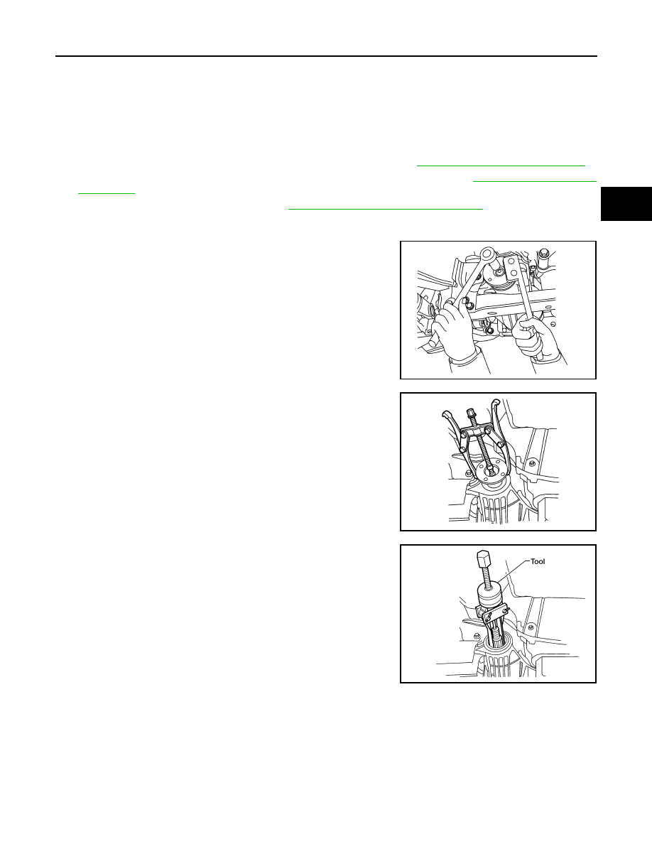
4. Remove the drive pinion lock nut using suitable tool.
5. Put matching marks on the companion flange and drive pinion

using paint.

CAUTION:

Use paint to make the matching marks. Do not damage the

companion flange or drive pinion.

6. Remove the companion flange using suitable tool.

7. Remove the front oil seal using Tool.

INSTALLATION

BDIA0001E

LDIA0171E

Tool number

: KV381054S0 (J-34286)

LDIA0172E

2010 Pathfinder

DLN-350

< ON-VEHICLE REPAIR >

[FRONT FINAL DRIVE: R180A]

FRONT OIL SEAL

1. Apply multi-purpose grease to the lips and differential gear oil to

the circumference of the new front oil seal. Then drive the new

front oil seal in evenly until it becomes flush with the gear carrier

using Tools.

CAUTION:

• Do not reuse front oil seal.

• Do not incline the new front oil seal when installing.

• Apply multi-purpose grease to the lips and differential

gear oil to the circumference of the new front oil seal.

2. Install the companion flange to the drive pinion while aligning the matching marks.
3. Apply anti-corrosive oil to the threads of the drive pinion and the

seating surface of the new drive pinion lock nut. Then adjust the

drive pinion lock nut tightening torque using suitable tool A, and

check the total preload torque using Tool B.

• The total preload torque should be within the total preload

torque specification. When not replacing the collapsible

spacer, it should also be equal to the measurement taken dur-

ing removal plus an additional 0.56 N·m (0.06 Kg-m, 5 in-lb).

• If the total preload torque is low, tighten the drive pinion lock

nut in 6.8 N·m (0.69 Kg-m, 5ft-lb) increments until the total pre-

load torque is met.

CAUTION:

• Do not reuse drive pinion lock nut.

• Apply anti-corrosive oil to the threads of the drive pinion

and the seating surface of the new drive pinion lock nut.

• Adjust the drive pinion lock nut tightening torque to the

lower limit first. Do not exceed the drive pinion lock nut

specified torque. Refer to 

DLN-356, "Disassembly and

Assembly"

.

• Do not loosen drive pinion lock nut to adjust the total preload torque. If the drive pinion lock nut

torque or the total preload torque exceeds the specifications, replace the collapsible spacer and

tighten it again to adjust. Refer to 

DLN-356, "Disassembly and Assembly"

.

• After adjustment, rotate drive pinion back and forth 2 to 3 times to check for unusual noise, rota-

tion malfunction, and other malfunctions.

4. Install new side oil seals into the front final drive assembly. Refer to 

DLN-351, "Removal and Installation"

.

5. Installation of the remaining components is in the reverse order of removal.

CAUTION:

Check the differential gear oil level after installation. Refer to 

DLN-348, "Checking Differential Gear

Oil"

.

Tool number

A: ST30720000 (J-25405)
B: ST27863000 ( — )

WDIA0147E

Tool number

B: ST3127S000 (J-25765-A)

Total preload torque: Refer to 

DLN-356, "Disassem-

bly and Assembly"

.

WDIA0381E

2010 Pathfinder

SIDE OIL SEAL

DLN-351

< ON-VEHICLE REPAIR >

[FRONT FINAL DRIVE: R180A]

C

E

F

G

H

I

J

K

L

M

A

B

DLN

N

O

P

SIDE OIL SEAL

Removal and Installation

INFOID:0000000005258478

REMOVAL

1. Remove the drive shafts from the front final drive assembly. Refer to 

FAX-7, "VQ40DE : Removal and

Installation"

.

2. Remove the side oil seal using suitable tool.

CAUTION:

Do not reuse the side oil seal.

INSTALLATION

1. Apply multi-purpose grease to the lips and differential gear oil to

the circumference of the new side oil seal. Then drive the new

side oil seal in evenly until it becomes flush with the gear carrier

using Tools.

CAUTION:

• Do not reuse side oil seal.

• Do not incline the new side oil seal when installing.

• Apply multi-purpose grease to the lips and differential

gear oil to the circumference of the new side oil seal.

2. Installation of the remaining components is in the reverse order of removal.

CAUTION:

Check the differential gear oil level after installation. Refer to 

DLN-348, "Checking Differential Gear

Oil"

.

LDIA0173E

Tool number

A: ST30720000 (J-25405)
B: ST27863000 ( — )

PDIA0826E

2010 Pathfinder

DLN-352

< ON-VEHICLE REPAIR >

[FRONT FINAL DRIVE: R180A]

CARRIER COVER

CARRIER COVER

Removal and Installation

INFOID:0000000005258479

REMOVAL

1. Remove the front final drive assembly. Refer to 

DLN-353, "Removal and Installation"

.

2. Remove the carrier cover bolts and separate the carrier cover

from the gear carrier using Tool.

CAUTION:

• Do not damage the mating surface.

• Do not insert flat-bladed screwdriver, this will damage the

mating surface.

INSTALLATION

1. Apply a 3 mm (0.12 in) bead of sealant to the mating surface of

the carrier cover as shown.

• Use Genuine Silicone RTV or equivalent. Refer to 

GI-14,

"Recommended Chemical Products and Sealants"

.

CAUTION:

Remove any old sealant adhering to the mating surfaces.

Also remove any moisture, oil, or foreign material adhering

to the application and mating surfaces.

2. Install the carrier cover to the gear carrier. Tighten the bolts to

the specified torque. Refer to 

DLN-356, "Disassembly and

Assembly"

.

3. Install the front final drive assembly. Refer to 

DLN-353,

"Removal and Installation"

.

CAUTION:

Fill the front final drive assembly with recommended differential gear oil. Refer to 

DLN-348

.

Tool number

: KV10111100 (J-37228)

PDIA0699E

PDIA0712E

2010 Pathfinder

FRONT FINAL DRIVE ASSEMBLY

DLN-353

< REMOVAL AND INSTALLATION >

[FRONT FINAL DRIVE: R180A]

C

E

F

G

H

I

J

K

L

M

A

B

DLN

N

O

P

REMOVAL AND INSTALLATION

FRONT FINAL DRIVE ASSEMBLY

Removal and Installation

INFOID:0000000005258480

REMOVAL

1. Drain the differential gear oil. Refer to 

DLN-348

.

2. Remove the drive shafts from the front final drive assembly. Refer to 

FAX-7, "VQ40DE : Removal and

Installation"

.

3. Remove the front crossmember.
4. Remove the front propeller shaft from the front final drive assembly. Refer to 

DLN-315, "Removal and

Installation"

.

5. Disconnect the vent hose from the front final drive assembly.

1.

Breather hose

2.

Front final drive assembly

3.

Front crossmember

Vehicle front

AWDIA0018GB

2010 Pathfinder

DLN-354

< REMOVAL AND INSTALLATION >

[FRONT FINAL DRIVE: R180A]

FRONT FINAL DRIVE ASSEMBLY

6. Support the front final drive assembly using a suitable jack.
7. Remove the front final drive assembly bolts, then remove the

front final drive assembly.

CAUTION:

Support the front final drive assembly while removing using

a suitable jack.

INSTALLATION

Installation is in the reverse order of removal.

• Install new side oil seals into the front final drive assembly. Refer to 

DLN-351, "Removal and Installation"

.

CAUTION:

• Make sure there are no pinched or restricted areas on the breather hose caused by folding or bend-

ing when installing it.

• Fill the front final drive assembly with differential gear oil after installation. Refer to 

DLN-348

.

WDIA0145E

2010 Pathfinder

FRONT FINAL DRIVE

DLN-355

< DISASSEMBLY AND ASSEMBLY >

[FRONT FINAL DRIVE: R180A]

C

E

F

G

H

I

J

K

L

M

A

B

DLN

N

O

P

DISASSEMBLY AND ASSEMBLY

FRONT FINAL DRIVE

Exploded View

INFOID:0000000005588048

1.

Drive pinion lock nut

2.

Companion flange

3.

Front oil seal

4.

Drive pinion front bearing

5.

Gear carrier

6.

Side oil seal

7.

Bushing

8.

Differential side shaft

9.

Differential side shaft bearing

10. Snap ring

11. Snap ring

12. Gasket

13. Drain plug

14. Collapsible spacer

15. Drive pinion rear bearing

16. Drive pinion height adjusting washer 17. Drive pinion

18. Side bearing adjusting washer

19. Side bearing

20. Side gear thrust washer

21. Side gear

22. Pinion mate shaft

23. Lock pin

24. Pinion mate gear

25. Pinion mate thrust washer

26. Drive gear

27. Differential case

28. Housing spacer

29. Side bearing cap

30. Filler plug

AWDIA0750GB

2010 Pathfinder

DLN-356

< DISASSEMBLY AND ASSEMBLY >

[FRONT FINAL DRIVE: R180A]

FRONT FINAL DRIVE

Disassembly and Assembly

INFOID:0000000005258481

ASSEMBLY INSPECTION AND ADJUSTMENT

• Drain the differential gear oil before inspection and adjustment. Refer to 

DLN-348

.

• Remove and install the carrier cover as necessary for inspection and adjustment. Refer to 

DLN-352

.

Total Preload Torque

1. Install the differential side shaft if necessary. Refer to 

DLN-351, "Removal and Installation"

.

CAUTION:

The differential side shaft must be installed in order to measure total preload torque. 

2. Rotate the drive pinion back and forth 2 to 3 times to check for unusual noise and rotation malfunction.
3. Rotate the drive pinion at least 20 times to check for smooth operation of the bearings.
4. Measure total preload torque using Tool.

NOTE:

Total preload torque = Drive pinion bearing preload torque +

Side bearing preload torque

• If the measured value is out of the specification, check and adjust each part. Adjust the drive pinion

bearing preload torque first, then adjust the side bearing preload torque.

CAUTION:

Select a side bearing adjusting washer for right and left individually.

Drive Gear Runout

1. Fit a dial indicator to the drive gear back face.
2. Rotate the drive gear to measure runout.

• If the runout is outside of the limit, check the condition of the drive

gear assembly. Foreign material may be caught between the drive

gear and differential case, or the differential case or drive gear may

be deformed.

CAUTION:

31. Carrier cover

A.

Seal lip

B.

Screw hole

C.

Refer to INSTALLATION

Tool number

: ST3127S000 (J-25765-A)

Total preload torque:

Refer to 

DLN-374, "Inspection 

and Adjustment"

PDIA0697E

If the total preload torque is greater than specification

On drive pinion bearings: Replace the collapsible spacer.
On side bearings:

Use thinner side bearing adjusting washers by the same 
amount on each side. Refer to 

DLN-374, "Inspection and Adjust-

ment"

.

If the total preload torque is less than specification

On drive pinion bearings: Tighten the drive pinion lock nut.
On side bearings:

Use thicker side bearing adjusting washers by the same 
amount on each side. Refer to 

DLN-374, "Inspection and Adjust-

ment"

.

Runout limit:

Refer to 

DLN-374, "Inspection and 

Adjustment"

SPD886

2010 Pathfinder


Content      ..     220      221      222      223     ..