Nissan Pathfinder (2010 year). Manual - part 211


  Index      Manuals     Nissan Pathfinder (2010 year) - Service and Repair Manual


Search            copyright infringement  


Content      ..     209      210      211      212     ..


Nissan Pathfinder (2010 year). Manual - part 211


ATP SWITCH

DLN-261

< SYMPTOM DIAGNOSIS >

[TRANSFER: TX15B]

C

E

F

G

H

I

J

K

L

M

A

B

DLN

N

O

P

ATP SWITCH

Description

INFOID:0000000005258425

The ATP indicator does not come on when the transfer is in neutral and the A/T lever is in neutral or, the ATP

indicator stays on when the transfer case is not in neutral.

Diagnosis Procedure

INFOID:0000000005258426

Regarding Wiring Diagram information, refer to 

DLN-240, "Wiring Diagram - PART TIME 4WD SYSTEM -"

.

1.

CHECK ATP SWITCH SIGNAL

With CONSULT-III

1. Start engine.

2. Select “DATA MONITOR” mode for “ALL MODE AWD/4WD” with CONSULT-III.

3. Read out the value of “ATP SWITCH”.

Without CONSULT-III

1. Start engine.

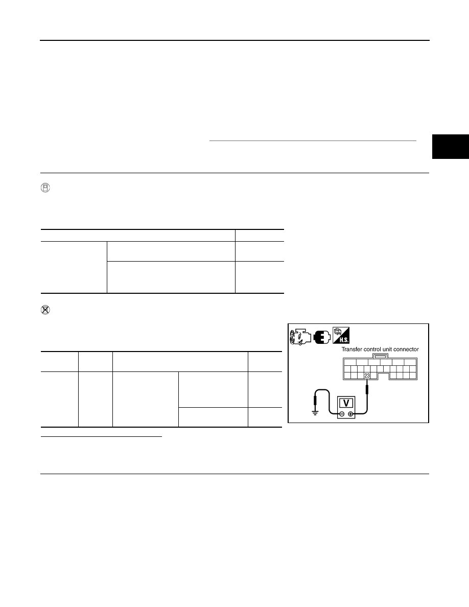
2. Check voltage between transfer control unit harness connector

terminal and ground.

Are the inspection results normal?

YES

>> GO TO 5.

NO

>> GO TO 2.

2.

CHECK HARNESS BETWEEN TRANSFER CONTROL UNIT AND ATP SWITCH

1. Turn ignition switch “OFF”.  (Stay for at least 5 seconds.)

2. Disconnect transfer control unit harness connector and the ATP switch harness connector.

Condition

Display value

• Vehicle stopped
• Engine running
• A/T selector lever 

“N” position

• Brake pedal de-

pressed

4WD shift switch: 4H to 4LO or 4LO to 4H
(While actuator motor is operating.)

ON

Except the above

OFF

Connector

Terminal

Condition

Voltage 

(Approx.)

M165

23 - 

Ground

• Vehicle stopped
• Engine running
• A/T selector lever 

“N” position

• Brake pedal de-

pressed

4WD shift switch: 4H 
to 4LO or 4LO to 4H
(While actuator motor 
is operating.)

0V

Except the above

Battery 
voltage

SDIA3375E

2010 Pathfinder

DLN-262

< SYMPTOM DIAGNOSIS >

[TRANSFER: TX15B]

ATP SWITCH

3. Check continuity between transfer control unit harness connec-

tor M165 terminal 23 and ATP switch harness connector F71

terminal 8.

Also check harness for short to ground and short to power.

Does continuity exist?

YES

>> GO TO 3.

NO

>> Repair or replace damaged parts.

3.

CHECK GROUND CIRCUIT

1. Turn ignition switch “OFF”.  (Stay for at least 5 seconds.)

2. Disconnect ATP switch harness connector.

3. Check continuity between ATP switch harness connector F71

terminal 9 and ground.

Also check harness for short to power.

Does continuity exist?

 YES  >> GO TO 4.

 NO

>> Repair open circuit or short to power in harness or con-

nectors.

4.

CHECK ATP SWITCH 

1. Turn ignition switch “OFF”.  (Stay for at least 5 seconds.)

2. Remove ATP switch. Refer to 

DLN-196, "Component Parts Location"

.

3. Push and release ATP switch and check continuity between ATP

switch terminals 8 and 9.

Are the inspection results normal?

YES

>> GO TO 5.

NO

>> Replace ATP switch.

5.

CHECK TRANSFER CONTROL UNIT

Check transfer control unit input/output signal. Refer to 

DLN-235, "Reference Value"

.

Are the inspection results normal?

YES

>> GO TO 6.

NO

>> Check transfer control unit pin terminals for damage or loose connection with harness connector.

If any items are damaged, repair or replace damaged parts.

6.

CHECK ATP WARNING LAMP

1. Turn ignition switch “ON”. (Do not start engine.)

2. A/T selector lever “N” position and engage the parking brake.

3. Switch 4WD shift switch from 4H to 4LO or 4LO to 4H.
Does the ATP warning lamp turn ON while the actuator motor is operating?

YES

>> Inspection End.

NO

>> Refer to 

DLN-257, "Diagnosis Procedure"

.

Continuity should exist.

SDIA3376E

Continuity should exist.

SDIA2394E

Terminal

Condition

Continuity

8 - 9

Push ATP switch

Yes

Release ATP switch

No

SDIA2395E

2010 Pathfinder

ATP SWITCH

DLN-263

< SYMPTOM DIAGNOSIS >

[TRANSFER: TX15B]

C

E

F

G

H

I

J

K

L

M

A

B

DLN

N

O

P

Component Inspection

INFOID:0000000005258427

1. Turn ignition switch “OFF”.  (Stay for at least 5 seconds.)
2. Disconnect ATP switch harness connector.
3. Remove ATP switch.  Refer to 

DLN-196, "Component Parts Location"

.

4. Push and release ATP switch and check continuity between ATP

switch terminals 8 and 9.

5. If the inspection results are abnormal replace the ATP switch.

Terminal

Condition

Continuity

8 - 9

Push ATP switch

Yes

Release ATP switch

No

SDIA2395E

2010 Pathfinder

DLN-264

< PRECAUTION >

[TRANSFER: TX15B]

PRECAUTIONS

PRECAUTION

PRECAUTIONS

Precaution for Supplemental Restraint System (SRS) "AIR BAG" and "SEAT BELT 
PRE-TENSIONER"

INFOID:0000000005550691

The Supplemental Restraint System such as “AIR BAG” and “SEAT BELT PRE-TENSIONER”, used along

with a front seat belt, helps to reduce the risk or severity of injury to the driver and front passenger for certain

types of collision. This system includes seat belt switch inputs and dual stage front air bag modules. The SRS

system uses the seat belt switches to determine the front air bag deployment, and may only deploy one front

air bag, depending on the severity of a collision and whether the front occupants are belted or unbelted.

Information necessary to service the system safely is included in the SR and SB section of this Service Man-

ual.

WARNING:

• To avoid rendering the SRS inoperative, which could increase the risk of personal injury or death in

the event of a collision which would result in air bag inflation, all maintenance must be performed by

an authorized NISSAN/INFINITI dealer.

• Improper maintenance, including incorrect removal and installation of the SRS, can lead to personal

injury caused by unintentional activation of the system. For removal of Spiral Cable and Air Bag

Module, see the SR section.

• Do not use electrical test equipment on any circuit related to the SRS unless instructed to in this

Service Manual. SRS wiring harnesses can be identified by yellow and/or orange harnesses or har-

ness connectors.

PRECAUTIONS WHEN USING POWER TOOLS (AIR OR ELECTRIC) AND HAMMERS

WARNING:

• When working near the Airbag Diagnosis Sensor Unit or other Airbag System sensors with the Igni-

tion ON or engine running, DO NOT use air or electric power tools or strike near the sensor(s) with a

hammer. Heavy vibration could activate the sensor(s) and deploy the air bag(s), possibly causing

serious injury.

• When using air or electric power tools or hammers, always switch the Ignition OFF, disconnect the

battery, and wait at least 3 minutes before performing any service.

Precaution Necessary for Steering Wheel Rotation After Battery Disconnect

INFOID:0000000005550692

NOTE:

• This Procedure is applied only to models with Intelligent Key system and NATS (NISSAN ANTI-THEFT SYS-

TEM).

• Remove and install all control units after disconnecting both battery cables with the ignition knob in the

LOCK

 position.

• Always use CONSULT-III to perform self-diagnosis as a part of each function inspection after finishing work.

If DTC is detected, perform trouble diagnosis according to self-diagnostic results.

For models equipped with the Intelligent Key system and NATS, an electrically controlled steering lock mech-

anism is adopted on the key cylinder.

For this reason, if the battery is disconnected or if the battery is discharged, the steering wheel will lock and

steering wheel rotation will become impossible.

If steering wheel rotation is required when battery power is interrupted, follow the procedure below before

starting the repair operation.

OPERATION PROCEDURE

1. Connect both battery cables.

NOTE:

Supply power using jumper cables if battery is discharged.

2. Use the Intelligent Key or mechanical key to turn the ignition switch to the 

ACC

 position. At this time, the

steering lock will be released.

3. Disconnect both battery cables. The steering lock will remain released and the steering wheel can be

rotated.

4. Perform the necessary repair operation.

2010 Pathfinder

PRECAUTIONS

DLN-265

< PRECAUTION >

[TRANSFER: TX15B]

C

E

F

G

H

I

J

K

L

M

A

B

DLN

N

O

P

5. When the repair work is completed, return the ignition switch to the 

LOCK

 position before connecting

the battery cables. (At this time, the steering lock mechanism will engage.)

6. Perform a self-diagnosis check of all control units using CONSULT-III. 

Precaution for Transfer Assembly and Transfer Control Unit Replacement

INFOID:0000000005258429

When replacing transfer assembly or transfer control unit, check the 4WD shift indicator pattern and adjust-

ment of the position between transfer assembly and transfer control unit if necessary.

CHECK 4WD SHIFT INDICATOR PATTERN

1. Set 4WD shift switch to “2WD”, “4H”, “4LO”, “4H” and “2WD” in order. Stay at each switch position for at

least 2 seconds.

2. Confirm 4WD shift indicator lamp and 4LO indicator lamp are changed properly as follows.

• If OK, the position between transfer assembly and transfer control unit is correct.

• If NG, the position is different between transfer assembly and transfer control unit.

Adjust the position between transfer assembly and transfer control unit. Refer to pattern table below.

Transfer position adjustment pattern

NOTE:

Method of adjustment can be chosen voluntarily, according to location of 4WD shift switch.

METHOD FOR ADJUSTMENT WITH 4WD SHIFT SWITCH AT “2WD”

Select Adjustment Pattern

1. Start engine. Run engine for at least 10 seconds.
2. Check 4WD shift indicator lamp and 4LO indicator lamp.

Pattern A

1. Stop vehicle and move A/T selector lever to “N” position with brake pedal depressed. Stay in "N" for at

least 2 seconds.

2. Turn 4WD shift switch to “4LO” position. Stay in "4LO" for at least 2 seconds.
3. Turn ignition switch “OFF”.
4. Start engine.
5. Erase self-diagnosis. Refer to 

DLN-200, "CONSULT-III Function (ALL MODE AWD/4WD)"

.

WDIA0137E

4WD shift switch condition

Refer procedure

4WD shift switch is under “2WD” condition when engine is being stopped.

"METHOD FOR ADJUSTMENT WITH 4WD SHIFT 

SWITCH AT “2WD”"

4WD shift switch is under “4H” or “4LO” condition when engine is being stopped.

"METHOD FOR ADJUSTMENT WITH 4WD SHIFT 

SWITCH AT “4H” OR “4LO”"

Indicator lamp condition

Refer procedure

When 4WD shift indicator lamp or 4LO indicator lamp is flashing.

"Pattern A"

Except for above.

"Pattern B"

2010 Pathfinder

DLN-266

< PRECAUTION >

[TRANSFER: TX15B]

PRECAUTIONS

6. Check 4WD shift indicator lamp and 4LO indicator lamp again. Refer to "CHECK 4WD SHIFT INDICATOR

PATTERN".

If 4WD shift indicator lamp and 4LO indicator lamp do not indicate proper pattern, install new transfer con-

trol unit and retry the above check.

Pattern B

1. Stop vehicle and move A/T selector lever to “N” position with brake pedal depressed. Stay in "N" for at

least 2 seconds.

2. Turn ignition switch “OFF”.
3. Start engine.
4. Erase self-diagnosis. Refer to 

DLN-200, "CONSULT-III Function (ALL MODE AWD/4WD)"

.

5. Check 4WD shift indicator lamp and 4LO indicator lamp again. Refer to "CHECK 4WD SHIFT INDICATOR

PATTERN".

If 4WD shift indicator lamp and 4LO indicator lamp do not indicate proper pattern, install new transfer con-

trol unit and retry the above check.

METHOD FOR ADJUSTMENT WITH 4WD SHIFT SWITCH AT “4H” OR “4LO”

1. Start engine. Run the engine for at least 10 seconds.
2. Stop vehicle and move A/T selector lever to “N” position with brake pedal depressed. Stay in "N" for at

least 2 seconds.)

3. Turn 4WD shift switch to “2WD” position. Stay in "2WD" for at least 2 seconds.
4. Turn ignition switch “OFF”.
5. Start engine.
6. Erase self-diagnosis. Refer to 

DLN-200, "CONSULT-III Function (ALL MODE AWD/4WD)"

.

7. Check 4WD shift indicator lamp and 4LO indicator lamp again. Refer to "CHECK 4WD SHIFT INDICATOR

PATTERN".

If 4WD shift indicator lamp and 4LO indicator lamp do not indicate proper pattern, install new transfer con-

trol unit and retry the above check.

Precaution

INFOID:0000000005258431

Before connecting or disconnecting the transfer control unit

harness connector, turn ignition switch “OFF” and disconnect

the battery cables. Battery voltage is applied to transfer con-

trol unit even if ignition switch is turned “OFF”.

When connecting or disconnecting pin connectors into or

from transfer control unit, take care not to damage pin termi-

nals (bend or break).

When connecting pin connectors make sure that there are not

any bends or breaks on transfer control unit pin terminals.

SEF289H

SEF291H

2010 Pathfinder

PRECAUTIONS

DLN-267

< PRECAUTION >

[TRANSFER: TX15B]

C

E

F

G

H

I

J

K

L

M

A

B

DLN

N

O

P

Before replacing transfer control unit, perform transfer con-

trol unit input/output signal inspection and make sure transfer

control unit functions properly. Refer to 

DLN-235, "Reference

Value"

.

Service Notice

INFOID:0000000005258432

• After overhaul refill the transfer with new transfer fluid.

• Check the fluid level or replace the fluid only with the vehicle parked on level ground.

• During removal or installation, keep inside of transfer clear of dust or dirt.

• Disassembly should be done in a clean work area.

• Before proceeding with disassembly, thoroughly clean the transfer. It is important to prevent the internal

parts from becoming contaminated by dirt or other foreign matter.

• Check for the correct installation status prior to removal or disassembly. If matchmarks are required, be cer-

tain they do not interfere with the function of the parts when applied.

• All parts should be carefully cleaned with a general purpose, non-flammable solvent before inspection or

reassembly.

• Check appearance of the disassembled parts for damage, deformation, and unusual wear. Replace them

with a new ones if necessary.

• Gaskets, seals and O-rings should replaced any time the transfer is disassembled.

• In principle, tighten bolts or nuts gradually in several steps working diagonally from inside to outside. If tight-

ening sequence is specified, use it.

• Observe the specified torque when assembling.

• Clean and flush the parts sufficiently and blow-dry them.

• Be careful not to damage sliding surfaces and mating surfaces.

• Use lint-free cloth or towels for wiping parts clean. Common shop rags can leave fibers that could interfere

with the operation of the transfer.

MEF040DB

2010 Pathfinder

DLN-268

< PREPARATION >

[TRANSFER: TX15B]

PREPARATION

PREPARATION

PREPARATION

Special Service Tool

INFOID:0000000005258433

The actual shapes of Kent-Moore tools may differ from those of special service tools illustrated here.

Tool number
(Kent-Moore No.)
Tool name

Description

ST33290001
(J-34286)
Puller

• Removing front oil seal
• Removing rear oil seal
• Removing metal bushing

KV38100500
(

)

Drift

• Installing front oil seal
• Installing rear oil seal
• Installing rear bearing
• Installing front bearing

a: 80 mm (3.15 in) dia.
b: 60 mm (2.36 in) dia.

KV40105310
(

)

Drift

• Installing dust cover

a: 89 mm (3.50 in) dia.
b: 80.7 mm (3.17 in) dia.

KV38100200
(

)

Drift

• Removing sun gear assembly and planetary 

carrier assembly

• Removing input bearing
• Installing sun gear assembly and planetary 

carrier assembly

a: 65 mm (2.56 in) dia.
b: 49 mm (1.93 in) dia.

ST30720000
(J-25405)
Drift

• Installing input bearing
• Installing input oil seal
• Installing carrier bearing

a: 77 mm (3.03 in) dia.
b: 55 mm (2.17 in) dia.

KV32102700
(

)

Drift

• Installing mainshaft rear bearing

a: 48 mm (1.89 in) dia.
b: 41 mm (1.61 in) dia.

ZZA0601D

ZZA0811D

ZZA1003D

ZZA1143D

ZZA0811D

ZZA0534D

2010 Pathfinder


Content      ..     209      210      211      212     ..