Nissan Pathfinder (2010 year). Manual - part 181
4WD SYSTEM
DLN-21
< FUNCTION DIAGNOSIS >
[TRANSFER: ATX14B]
C
E
F
G
H
I
J
K
L
M
A
B
DLN
N
O
P
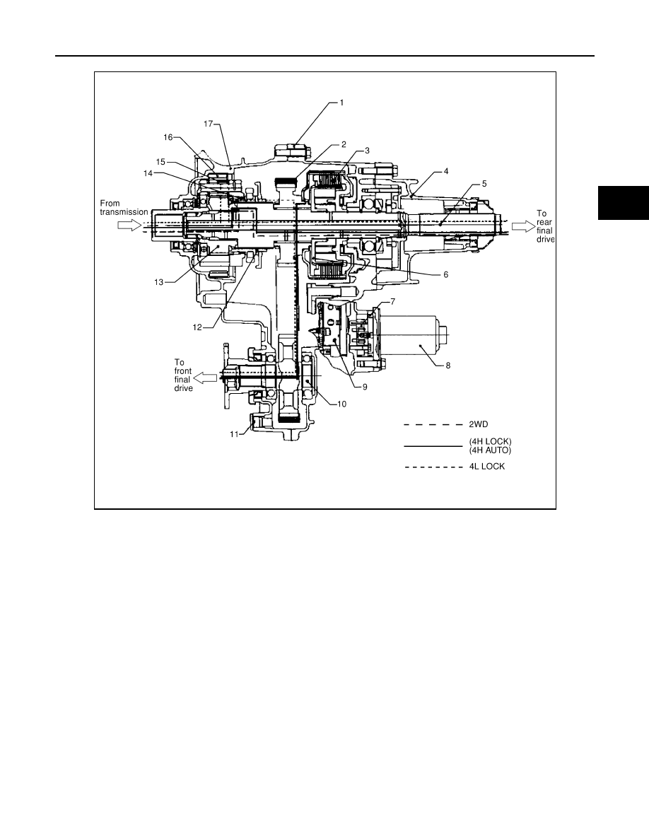
POWER TRANSFER FLOW
1.
Center case
2.
Chain
3.
Multiple disc clutch
4.
Rear case
5.
Mainshaft
6.
Clutch hub assembly
7.
Sub oil pump
8.
Transfer motor
9.
Control valve
10. Front drive shaft
11. Drain plug
12. 2-4 sleeve
13. Sun gear assembly
14. L-H sleeve
15. Planetary carrier assembly
16. Internal gear
17. Front case
LDIA0053E
2010 Pathfinder