Nissan Pathfinder (2010 year). Manual - part 168
DOOR LOCK ACTUATOR
DLK-243
< COMPONENT DIAGNOSIS >
[WITHOUT INTELLIGENT KEY SYSTEM]
C
D
E
F
G
H
I
J
L
M
A
B
DLK
N
O
P
1.
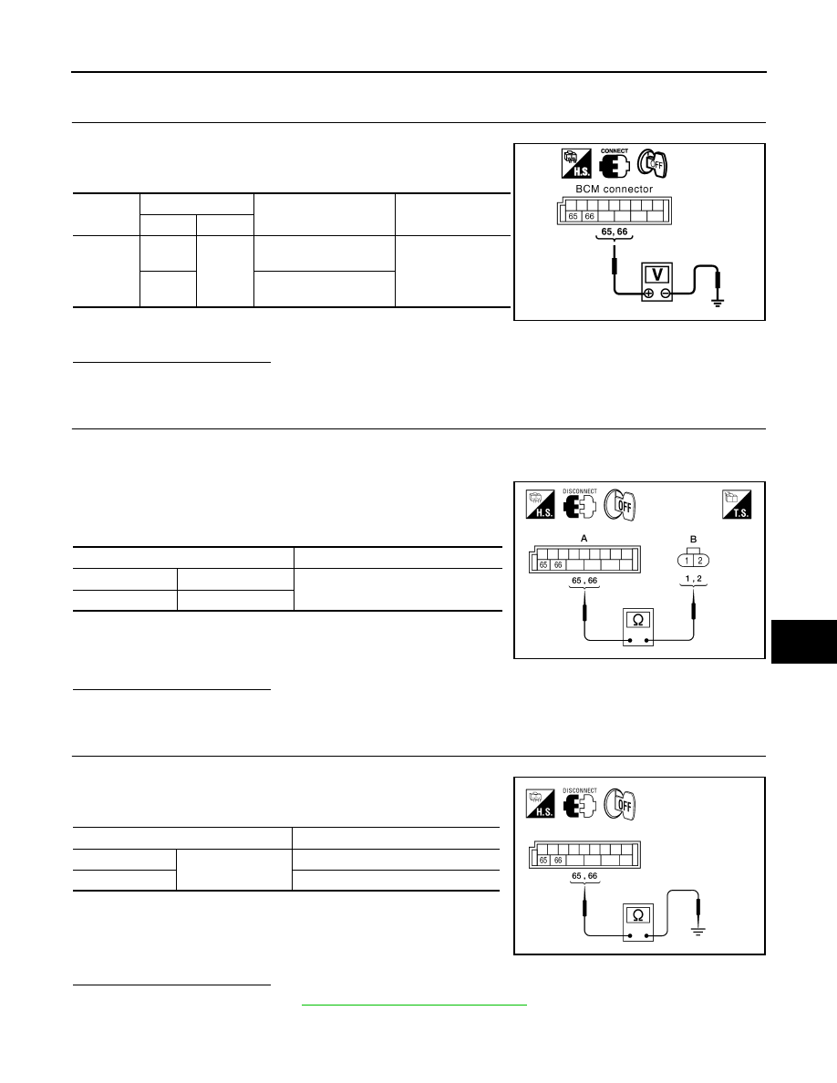
CHECK DOOR LOCK ACTUATOR SIGNAL
1. Turn ignition switch OFF.
2. Check voltage between BCM connector M20 terminals 65, 66
and ground.
Is the inspection result normal?
YES
>> GO TO 2
NO
>> GO TO 3
2.
CHECK DOOR LOCK ACTUATOR HARNESS
NOTE:
The passenger select unlock relay must remain connected during this test.
1. Disconnect BCM and rear door lock actuator LH.
2. Check continuity between BCM connector (A) M20 terminals 65,
66 and rear door lock actuator LH connector (B) D205 terminals
1, 2.
Is the inspection result normal?
YES
>> Replace rear door lock actuator LH.
NO
>> Repair or replace harness or passenger select unlock relay.
3.
CHECK DOOR LOCK ACTUATOR HARNESS
1. Disconnect BCM and each door lock actuator.
2. Check continuity between BCM connector M20 terminals 65, 66
and ground.
Is the inspection result normal?
YES
>> Replace BCM. Refer to
BCS-59, "Removal and Installation"
NO
>> Repair or replace harness or passenger select unlock relay.
REAR RH
Connector
Terminals
Condition
Voltage (V)
(Approx.)
(+)
(-)
M20
65
Ground
Door lock/unlock switch
is turned to LOCK
0
→
Battery voltage
for 300 ms
66
Door lock/unlock switch
is turned to UNLOCK
LIIA1048E
Terminals
Continuity
65
2
Yes
66
1
ALKIA1192ZZ
Terminals
Continuity
65
Ground
No
66
No
ALKIA0631ZZ
2010 Pathfinder