Nissan Pathfinder (2010 year). Manual - part 144
LUGGAGE AREA ANTENNA
DLK-51
< COMPONENT DIAGNOSIS >
[WITH INTELLIGENT KEY SYSTEM]
C
D
E
F
G
H
I
J
L
M
A
B
DLK
N
O
P
LUGGAGE AREA ANTENNA
Description
INFOID:0000000005259878
Detects whether Intelligent Key is inside the vehicle.
Component Function Check
INFOID:0000000005259879
1.
CHECK INSIDE KEY ANTENNA INPUT SIGNAL
With CONSULT-III
1. Check “ANTENNA” in “Active Test” mode with CONSULT-III.
2. Touch “ROOM ANT2”.
3. When Intelligent Key is inside luggage area antenna detection area, hazard lamps flash.
Is the inspection result normal?
YES
>> luggage area antenna is OK.
NO
>> Refer to
.
Diagnosis Procedure
INFOID:0000000005259880
Regarding Wiring Diagram information, refer to
DLK-149, "Wiring Diagram — INTELLIGENT KEY SYSTEM —
1.
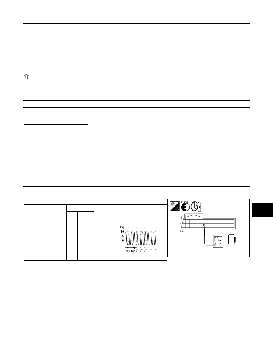
CHECK INSIDE KEY ANTENNA POWER SUPPLY SIGNAL
1. Turn ignition switch OFF.
2. Check signal between Intelligent Key unit connector and ground with an oscilloscope.
Is the inspection result normal?
YES
>> Luggage area antenna is OK.
NO
>> GO TO 2
2.
CHECK INSIDE KEY ANTENNA
1. Disconnect Intelligent Key unit connector and luggage area antenna connectors.
2. Check continuity between Intelligent Key unit harness connector (A) M164 terminals 33, 34 and luggage
area antenna harness connector (B) B129 terminals 1, 2.
Test Item
Condition
Possible cause
ROOM ANT2
An excessive high or low voltage from inside
antenna is sent to the Intelligent Key Unit
• Luggage area antenna
• Between Intelligent Key unit and luggage area antenna
Connector
Item
Terminals
Condition
Signal (V)
(Reference value)
(+)
(–)
M164
Intelligent
Key unit
33
Ground
Ignition
switch is
pushed.
ALKIA0589ZZ
PIIB7441E
2010 Pathfinder