Nissan Pathfinder (2010 year). Manual - part 81


  Index      Manuals     Nissan Pathfinder (2010 year) - Service and Repair Manual


Search            copyright infringement  


Content      ..     79      80      81      82     ..


Nissan Pathfinder (2010 year). Manual - part 81


AV

NORMAL OPERATING CONDITION

AV-455

< SYMPTOM DIAGNOSIS >

[BOSE AUDIO WITH NAVIGATION]

C

D

E

F

G

H

I

J

K

L

M

B

A

O

P

Location Correction by Map-Matching is Slow

• The map-matching function needs to refer to the data of the surrounding area. It is necessary to drive some

distance for the function to work.

• Because map-matching operates on this principle, when there are many roads running in similar directions

in the surrounding area, no matching determination may be made. The location may not be corrected until

some special feature is found.

Name of Road is Not Displayed

The current road name may not be displayed if there are no road names displayed on the map screen.

Contents of Display Differ for Birdview™ and the (Flat) Map Screen

Difference of the BIRDVIEW™ screen from the flat map screen are as follows.

• The current place name displays names which are primarily in the direction of vehicle travel.

• The amount of time before the vehicle travel or turn angle is updated on the screen is longer than for the

(flat) map display.

• The conditions for display of place names, roads, and other data are different for nearby areas and for more

distant areas.

• Some thinning of the character data is done to prevent the display becoming too complex. In some cases

and in some locations, the display contents may differ.

• The same place name, street name, etc. may be displayed multiple times.

Vehicle Mark Shows a Position Which is Completely Wrong

In the following cases, the vehicle mark may appear on completely different position in the map depending on

the GPS satellite signal receiving conditions. In this case, perform location correction and direction correction.

• When location correction has not been done

- If the receiving conditions of the GPS satellite signal is poor, if the vehicle mark becomes out of place, it may

move to a completely different location and not come back if location correction is not done. The position will

be corrected if the GPS signal can be received.

• When the vehicle has traveled by ferry, or when the vehicle has been being towed

Precautions 
for driving

Just after the engine is started

If the vehicle is driven just after the engine 
is started when the gyroscope (angular 
speed sensor) correction is not completed, 
the vehicle can lose its direction and may 
have deviated from the correct location.

Wait for a short while before 
driving after starting the engine.

Continuous driving without stopping

When driving long distances without stop-
ping, direction errors may accumulate, and 
the current-location mark may deviate from 
the correct road.

Stop and adjust the orientation.

Abusive driving

Spinning the wheels or engaging in other 
kinds of abusive driving may result in the 
system being unable perform correct detec-
tion, and may cause the vehicle mark to de-
viate from the correct road.

If after travelling about 10 km (6 
miles) the correct location has 
not been restored, perform lo-
cation correction and, if neces-
sary, direction correction.
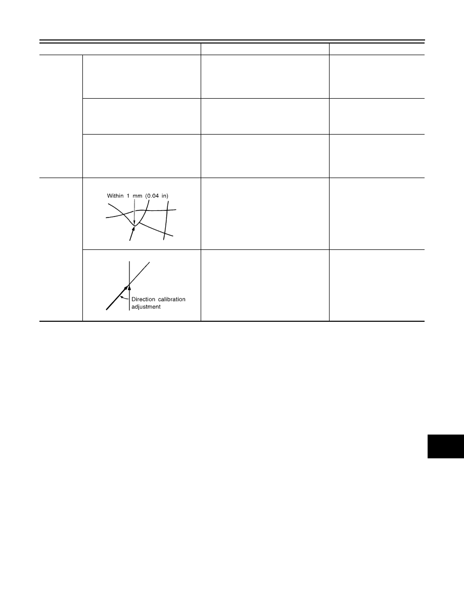
How to cor-
rect location

Position correction accuracy

If the accuracy of location settings is poor, 
accuracy may be reduced when the correct 
road cannot be found, particularly in places 
where there are many roads.

Enter in the road displayed on 
the screen with an accuracy of 
approx. 1mm.
Caution: Whenever possible, 
use detailed map for the correc-
tion.

Direction when location is corrected

If the accuracy of location settings during 
correction is poor, accuracy may be re-
duced afterwards.

Perform direction correction.

Cause (condition) –: While driving ooo: Display

Driving condition

Remarks (correction, etc.)

SEL701V

SEL702V

2010 Pathfinder

2010 Pathfinder

AV-456

< SYMPTOM DIAGNOSIS >

[BOSE AUDIO WITH NAVIGATION]

NORMAL OPERATING CONDITION

- Because calculation of the current location cannot be done when traveling with the ignition off, for example

when traveling by ferry or when being towed, the location before travel is displayed. If the precise location

can be detected with GPS, the location will be corrected.

Vehicle Mark Jumps

In the following cases, the vehicle mark may appear to jump as a result of automatic correction of the current

location.

• When map matching has been done

- If the current location and the vehicle mark are different when map matching is done, the vehicle mark may

seem to jump. At this time, the location may be “corrected” to the wrong road or to a location which is not on

a road.

• When GPS location correction has been done

- If the current location and the vehicle mark are different when the location is corrected using GPS measure-

ments, the vehicle mark may seem to jump. At this time, the location may be “corrected” to a location which

is not on a road.

Vehicle Mark is in a River or Sea

The navigation system moves the vehicle mark with no distinction between land and rivers or sea. If the vehi-

cle mark is somehow out of place, it may appear that the vehicle is driving in a river or the sea.

Vehicle Mark Automatically Rotates

The system wrongly memorizes the rotating status as stopping when the ignition switch is turned ON with the

turntable rotating. That causes the vehicle mark to rotate when the vehicle is stopped.

When Driving on Same Road, Sometimes Vehicle Mark is in Right Place and Sometimes it is in Wrong Place

The conditions of the GPS antenna (GPS data) and gyroscope (angular speed sensor) change gradually.

Depending on the road traveled and the operation of the steering wheel, the location detection results will be

different. Therefore, even on a road on which the location has never been wrong, conditions may cause the

vehicle mark to deviate.

2010 Pathfinder

2010 Pathfinder

AV

PRECAUTIONS

AV-457

< PRECAUTION >

[BOSE AUDIO WITH NAVIGATION]

C

D

E

F

G

H

I

J

K

L

M

B

A

O

P

PRECAUTION

PRECAUTIONS

Precaution for Supplemental Restraint System (SRS) "AIR BAG" and "SEAT BELT 
PRE-TENSIONER"

INFOID:0000000005259624

The Supplemental Restraint System such as “AIR BAG” and “SEAT BELT PRE-TENSIONER”, used along

with a front seat belt, helps to reduce the risk or severity of injury to the driver and front passenger for certain

types of collision. This system includes seat belt switch inputs and dual stage front air bag modules. The SRS

system uses the seat belt switches to determine the front air bag deployment, and may only deploy one front

air bag, depending on the severity of a collision and whether the front occupants are belted or unbelted.

Information necessary to service the system safely is included in the SR and SB section of this Service Man-

ual.

WARNING:

• To avoid rendering the SRS inoperative, which could increase the risk of personal injury or death in

the event of a collision which would result in air bag inflation, all maintenance must be performed by

an authorized NISSAN/INFINITI dealer.

• Improper maintenance, including incorrect removal and installation of the SRS, can lead to personal

injury caused by unintentional activation of the system. For removal of Spiral Cable and Air Bag

Module, see the SR section.

• Do not use electrical test equipment on any circuit related to the SRS unless instructed to in this

Service Manual. SRS wiring harnesses can be identified by yellow and/or orange harnesses or har-

ness connectors.

PRECAUTIONS WHEN USING POWER TOOLS (AIR OR ELECTRIC) AND HAMMERS

WARNING:

• When working near the Airbag Diagnosis Sensor Unit or other Airbag System sensors with the Igni-

tion ON or engine running, DO NOT use air or electric power tools or strike near the sensor(s) with a

hammer. Heavy vibration could activate the sensor(s) and deploy the air bag(s), possibly causing

serious injury.

• When using air or electric power tools or hammers, always switch the Ignition OFF, disconnect the

battery, and wait at least 3 minutes before performing any service.

Precaution Necessary for Steering Wheel Rotation After Battery Disconnect

INFOID:0000000005259625

NOTE:

• This Procedure is applied only to models with Intelligent Key system and NATS (NISSAN ANTI-THEFT SYS-

TEM).

• Remove and install all control units after disconnecting both battery cables with the ignition knob in the

LOCK

 position.

• Always use CONSULT-III to perform self-diagnosis as a part of each function inspection after finishing work.

If DTC is detected, perform trouble diagnosis according to self-diagnostic results.

For models equipped with the Intelligent Key system and NATS, an electrically controlled steering lock mech-

anism is adopted on the key cylinder.

For this reason, if the battery is disconnected or if the battery is discharged, the steering wheel will lock and

steering wheel rotation will become impossible.

If steering wheel rotation is required when battery power is interrupted, follow the procedure below before

starting the repair operation.

OPERATION PROCEDURE

1. Connect both battery cables.

NOTE:

Supply power using jumper cables if battery is discharged.

2. Use the Intelligent Key or mechanical key to turn the ignition switch to the 

ACC

 position. At this time, the

steering lock will be released.

3. Disconnect both battery cables. The steering lock will remain released and the steering wheel can be

rotated.

4. Perform the necessary repair operation.

2010 Pathfinder

2010 Pathfinder

AV-458

< PRECAUTION >

[BOSE AUDIO WITH NAVIGATION]

PRECAUTIONS

5. When the repair work is completed, return the ignition switch to the 

LOCK

 position before connecting

the battery cables. (At this time, the steering lock mechanism will engage.)

6. Perform a self-diagnosis check of all control units using CONSULT-III. 

Precaution for Trouble Diagnosis

INFOID:0000000005259626

AV COMMUNICATION SYSTEM

• Do not apply voltage of 7.0 V or higher to the measurement terminals.

• Use the tester with its open terminal voltage being 7.0 V or less.

• Be sure to turn ignition switch OFF and disconnect the battery cable from the negative terminal before

checking the circuit.

Precaution for Harness Repair

INFOID:0000000005259627

AV COMMUNICATION SYSTEM

• Solder the repaired parts, and wrap with tape. [Frays of twisted line

must be within 110 mm (4.33 in).]

• Do not perform bypass wire connections for the repair parts. (The

spliced wire will become separated and the characteristics of

twisted line will be lost.)

PKIA0306E

PKIA0307E

2010 Pathfinder

2010 Pathfinder

AV

PREPARATION

AV-459

< PREPARATION >

[BOSE AUDIO WITH NAVIGATION]

C

D

E

F

G

H

I

J

K

L

M

B

A

O

P

PREPARATION

PREPARATION

Commercial Service Tools

INFOID:0000000005259628

Tool name

Description

Power tool

Loosening bolts and nuts

PBIC0191E

2010 Pathfinder

2010 Pathfinder

AV-460

< ON-VEHICLE REPAIR >

[BOSE AUDIO WITH NAVIGATION]

AV CONTROL UNIT

ON-VEHICLE REPAIR

AV CONTROL UNIT

Removal and Installation

INFOID:0000000005259629

AUDIO UNIT 

1.

Cluster lid C

2.

AV switch assembly

3.

AV control unit

4.

AV control unit brackets

5.

Tuner knob switch

6.

A/C and AV switch assembly

7.

Volume knob switch

8.

Volume knob

9.

Temp knobs RH and LH

10. Enter button

11. Tuner knob

ALNIA0361ZZ

2010 Pathfinder

2010 Pathfinder

AV

AV CONTROL UNIT

AV-461

< ON-VEHICLE REPAIR >

[BOSE AUDIO WITH NAVIGATION]

C

D

E

F

G

H

I

J

K

L

M

B

A

O

P

CAUTION:

Only remove and replace the A/C or AV switch assembly knobs if damaged or missing. The knobs

must not be removed from switches when removing and installing the A/C or AV switch assembly to

prevent damage to the switch assembly.

REMOVAL

1. Disconnect the battery negative terminal.
2. Remove the cluster lid C. Refer to 

IP-12, "Removal and Installation"

.

3. Remove the AV control unit screws, using a power tool.
4. Remove the AV control unit.
5. Remove the A/C and AV switch assembly screws, then remove the A/C and AV switch assemblies as nec-

essary.

INSTALLATION

Installation is in the reverse order of removal.

2010 Pathfinder

2010 Pathfinder

AV-462

< ON-VEHICLE REPAIR >

[BOSE AUDIO WITH NAVIGATION]

DISPLAY UNIT

DISPLAY UNIT

Removal and Installation

INFOID:0000000005259630

REMOVAL

1. Remove Cluster lid C. Refer to 

IP-12, "Removal and Installation"

.

2. Remove the display unit screws (A). 
3. Pull out the display unit (1), then disconnect the display unit con-

nectors and remove the display unit (1).

4. Remove the A/C auto amp.screws (A), remove the (C103) fas-

teners (B) from the display unit assembly brackets and remove

the A/C auto amp. (1).

5. Remove the display unit bracket unit screws (C) and remove the

display unit brackets (2).

INSTALLATION

Installation is in reverse order of removal.

ALNIA0358ZZ

ALNIA0359ZZ

2010 Pathfinder

2010 Pathfinder


Content      ..     79      80      81      82     ..