Nissan Pathfinder (2010 year). Manual - part 12
ADP-82
< COMPONENT DIAGNOSIS >
PEDAL ADJUSTING SENSOR
1. Turn ignition switch OFF.
2. Disconnect automatic drive positioner control unit and pedal
adjusting motor assembly.
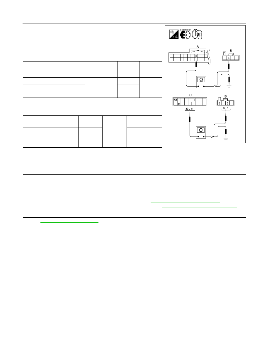
3. Check continuity between automatic drive positioner control unit
harness connector and pedal adjusting motor assembly harness
connector.
4. Check continuity between automatic drive positioner control unit
harness connector and ground.
Is the inspection result normal?
YES
>> GO TO 3
NO
>> Repair or replace harness.
3.
CHECK DOOR MIRROR OPERATION
1. Connect automatic drive positioner control unit and pedal adjusting motor assembly.
2. Turn ignition switch ON.
3. Check door mirror operation with memory function.
Is the operation normal?
YES
>> Replace pedal adjusting motor assembly. Refer to
BR-23, "Removal and Installation"
NO
>> Replace automatic drive positioner control unit. Refer to
ADP-162, "Removal and Installation"
4.
CHECK INTERMITTENT INCIDENT
GI-37, "Intermittent Incident"
Is the inspection result normal?
YES
>> Replace automatic drive positioner control unit. Refer to
ADP-162, "Removal and Installation"
NO
>> Repair or replace the malfunctioning part.
Automatic drive posi-
tioner
control unit connector
Terminal
Pedal adjusting
motor assembly
connector
Terminal
Continuity
M33 (A)
8
E110 (B)
4
Yes
M34 (C)
33
5
41
3
Automatic drive positioner
control unit connector
Terminal
Ground
Continuity
M33 (A)
8
No
M34 (C)
33
41
LIIA2236E
2010 Pathfinder