Nissan Pathfinder (2009 year). Manual - part 563
RSU-10
< ON-VEHICLE REPAIR >
REAR SUSPENSION ASSEMBLY
ON-VEHICLE REPAIR
REAR SUSPENSION ASSEMBLY
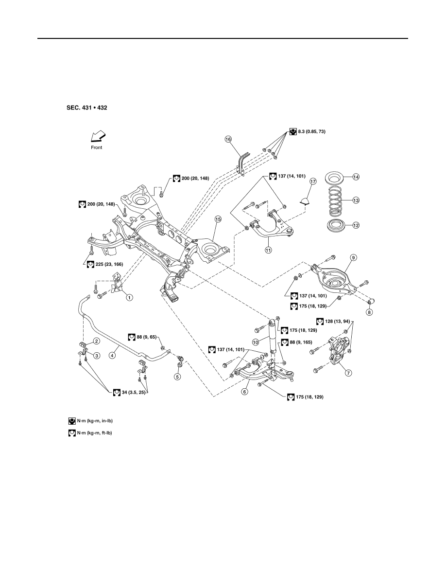
Component
INFOID:0000000003937654
1.
Seat belt latch anchor
2.
Stabilizer bar bushing
3.
Stabilizer bar clamp
4.
Stabilizer bar
5.
Connecting rod
6.
Front lower link
7.
Knuckle
8.
Bushing
9.
Rear lower link
10. Shock absorber
11.
Suspension arm
12. Lower rubber seat
13. Coil spring
14. Upper rubber seat
15. Rear suspension member
16. Spare tire bracket
17. Bound bumper
AWEIA0022GB
2009 Pathfinder