Nissan Pathfinder (2009 year). Manual - part 489
IP-16
< DISASSEMBLY AND ASSEMBLY >
CENTER CONSOLE ASSEMBLY
DISASSEMBLY AND ASSEMBLY
CENTER CONSOLE ASSEMBLY
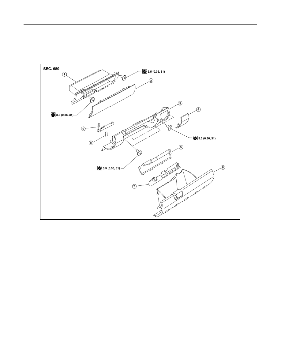
Exploded View
INFOID:0000000003938790
Disassembly and Assembly
INFOID:0000000003938791
LOWER GLOVE BOX
Disassembly
1.
Remove fuse block cover.
2.
Remove damper hook.
3.
Remove lower glove box latch cover.
4.
Remove lower glove box latch assembly.
Assembly
Assembly is in the reverse order of disassembly.
UPPER GLOVE BOX
Disassembly
1.
Remove upper glove box door screws.
2.
Remove upper glove box door.
1.
Upper glove box
2.
Upper glove box door
3.
Lower instrument panel RH
4.
Fuse block cover
5.
Lower glove box latch assembly cover 6.
Lower glove box
7.
Lower glove box latch assembly
8.
Damper hook
9.
Lower glove box damper
WIIA1049E
2009 Pathfinder