Nissan Pathfinder (2009 year). Manual - part 431
 

  Index      Manuals     Nissan Pathfinder (2009 year) - Service and Repair Manual


Search            copyright infringement  


Content      ..     429      430      431      432     ..


Nissan Pathfinder (2009 year). Manual - part 431


FSU-20

< REMOVAL AND INSTALLATION >

KNUCKLE

7.

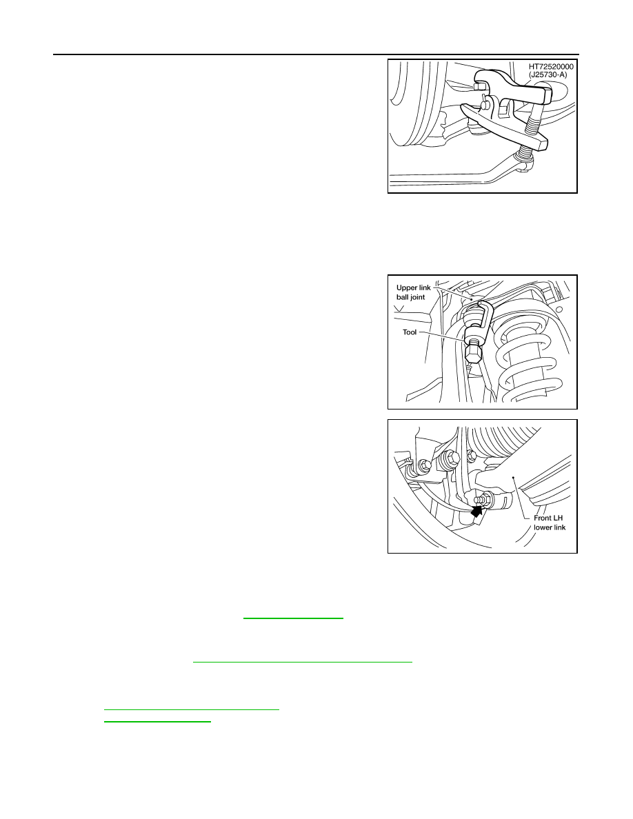
Disconnect steering outer socket from steering knuckle using
Tool. Be careful not to damage outer socket boot.

CAUTION:

To prevent damage to threads and to prevent Tool from
coming off suddenly, temporarily tighten nut. 

8.

Remove wheel hub and bearing assembly bolts using power tool.

9.

Remove splash guard and wheel hub and bearing assembly from steering knuckle.

CAUTION:

Do not pull on wheel sensor harness.

10. Remove cotter pin and nut from upper link ball joint.

11. Separate upper link ball joint from steering knuckle using Tool.

12. Remove pinch bolt from steering knuckle using power tool, then

separate lower link ball joint from steering knuckle.

13. Remove steering knuckle from vehicle.

INSPECTION AFTER REMOVAL

Check for deformity, cracks and damage on each part, replace if necessary.
• Perform ball joint inspection. Refer to 

FSU-10, "Inspection"

.

INSTALLATION

Installation is in the reverse order of removal.
• For 4WD models, refer to 

FAX-6, "VQ40DE : Removal and Installation"

 for drive shaft lock nut tightening

torque.

CAUTION:

Always replace drive shaft lock nut and cotter pin.

• Refer to 

ST-29, "Disassembly and Assembly"

 for outer socket nut tightening torque.

• Refer to 

FSU-13, "Component"

 for front suspension tightening torques.

Tool number

: HT72520000 (J-25730-A)

SDIA1434E

Tool number

: ST29020001 (J-24319-01)

WEIA0119E

LEIA0097E

2009 Pathfinder

KNUCKLE

FSU-21

< REMOVAL AND INSTALLATION >

C

D

F

G

H

I

J

K

L

M

A

B

FSU

N

O

P

• When installing disc rotor on wheel hub and bearing assembly,

align the marks.
NOTE:
When not using the alignment mark, refer to 

BR-57, "Front Disc

Brake"

.

• When installing wheel and tire, refer to 

WT-48, "Rotation"

.

• Perform wheel alignment. Refer to 

FSU-6, "Front Wheel Align-

ment"

.

WDIA0044E

2009 Pathfinder

FSU-22

< DISASSEMBLY AND ASSEMBLY >

COIL SPRING AND SHOCK ABSORBER

DISASSEMBLY AND ASSEMBLY

COIL SPRING AND SHOCK ABSORBER

Disassembly and Assembly

INFOID:0000000003939329

DISASSEMBLY

1.

Set the shock absorber in a vise, then loosen (without removing)
the piston rod lock nut as shown.

CAUTION:

Do not remove piston rod lock nut at this time.

2.

Compress the coil spring using commercial service tool until the
shock absorber mounting insulator can be turned by hand.

WARNING:

Make sure that the pawls of the two spring compressors are
firmly hooked on the coil spring. The spring compressors
must be tightened alternately and evenly so as not to tilt the
coil spring.

3.

Remove the piston rod lock nut.
• Discard the piston rod lock nut, use a new nut for assembly.

4.

Remove the components from the shock absorber.
• Keep the coil spring compressed in the commercial service

tool if reusing it for assembly.

INSPECTION AFTER DISASSEMBLY

Shock Absorber Assembly

• Check for smooth operation through a full stroke, both compression and extension.
• Check for oil leakage on welded or gland packing portions.
• Check piston rod for cracks, deformation or other damage and replace if necessary.

Mounting Insulator and Rubber Parts

Check cemented rubber-to-metal portion for separation or cracks. Check rubber parts for deterioration and
replace if necessary.

Coil Spring

• Check for cracks, deformation or other damage and replace if necessary.
• Check the coil spring free height.

ASSEMBLY

SSU002

SSU003

Front coil spring free height

2WD

: 345.4 mm (13.6 in)

4WD

: 356 mm (14.0 in)

2009 Pathfinder

COIL SPRING AND SHOCK ABSORBER

FSU-23

< DISASSEMBLY AND ASSEMBLY >

C

D

F

G

H

I

J

K

L

M

A

B

FSU

N

O

P

1.

When installing coil spring on strut, it must be positioned as
shown.

2.

Install the shock absorber mounting insulator as shown in line
with lower shock mount and step in lower seat.
• The step in the strut assembly lower seat faces outside of

vehicle.

3.

Tighten the new piston rod lock nut to specification. Refer to

FSU-13, "Component"

.

• Use a new piston rod lock nut for assembly.

4.

Remove commercial service tool.

SFA508A

WEIA0117E

2009 Pathfinder

FSU-24

< SERVICE DATA AND SPECIFICATIONS (SDS) 

SERVICE DATA AND SPECIFICATIONS (SDS)

SERVICE DATA AND SPECIFICATIONS (SDS)

SERVICE DATA AND SPECIFICATIONS (SDS)

General Specification (Front)

INFOID:0000000003939330

Spring Free Height

INFOID:0000000003939331

Unit: mm (in)

Wheel Alignment (Unladen*1)

INFOID:0000000003939332

*1: Fuel, radiator coolant and engine oil full. Spare tire, jack, hand tools and mats in designated positions.

Suspension type

Independent double wishbone coil over shock

Shock absorber type

Double-acting hydraulic

Stabilizer

Standard equipment

Drive type

2WD

4WD

Front spring free height

345.4 (13.6)

356 (14.0)

Drive type

2WD

4WD

Camber
Degree minute (decimal degree)

Minimum

-0

°

 30

 (-0.50

°

)

-0

°

 15

 (-0.25

°

)

Nominal

0

°

 15

 (0.25

°

)

0

°

 30

 (0.50

°

)

Maximum

1

°

 00

 (1.00

°

)

1

°

 15

 (1.25

°

)

Cross camber

0

°

 45

 (0.75

°

) or less

 0

°

 45

 (0.75

°

) or less

Caster
Degree minute (decimal degree)

Minimum

2

°

 15

 (2.25

°

)

2

°

 00

 (2.00

°

)

Nominal

3

°

 0

 (3.00

°

)

2

°

 45

 (2.75

°

)

Maximum

3

°

 45

 (3.75

°

)

3

°

 30

 (3.50

°

)

Cross caster

0

°

 45

 (0.75

°

) or less

0

°

 45

 (0.75

°

) or less

Kingpin inclination
Degree minute (decimal degree)

Nominal

13

°

 0

 (13.00

°

)

12

°

 45

 (12.75

°

)

Total toe-in

Distance (A 

 B)

Minimum

2.1 mm (0.08 in)

2.1 mm (0.08 in)

Nominal

3.1 mm (0.12 in)

3.1 mm (0.12 in)

Maximum

4.1 mm (0.16 in)

4.1 mm (0.16 in)

Angle (left wheel or right wheel)
Degree minute (decimal degree)

Minimum

0

°

 5

 (0.08

°

)

0

°

 5

 (0.08

°

)

Nominal

0

°

 7

 (0.12

°

)

0

°

 7

 (0.12

°

)

Maximum

0

°

 9

 (0.15

°

)

0

°

 9

 (0.15

°

)

Wheel turning angle (full turn)

Inside 
Degree minute (Decimal degree)

33

°

 26

 – 35

°

 26

 *

2

(33.43

°

 – 35.43

°

)

33

°

 33

 – 35

°

 33

 *

4

(33.55

°

 – 35.55

°

)

Outside
Degree minute (Decimal degree)

29

°

 22

 – 31

°

 22

 *

3

(29.37

°

 – 31.37

°

)

29

°

 38

 – 31

°

 38

 *

5

(29.63

°

 – 31.63

°

)

SFA234AC

2009 Pathfinder

SERVICE DATA AND SPECIFICATIONS (SDS)

FSU-25

< SERVICE DATA AND SPECIFICATIONS (SDS) 

C

D

F

G

H

I

J

K

L

M

A

B

FSU

N

O

P

*2: Target value 35

°

 26

 (35.43

°

)

*3: Target value 31

°

 22

 (31.37

°

)

*4: Target value 35

°

 33

 (35.55

°

)

*5: Target value 31

°

 38

 (31.63

°

)

Ball Joint

INFOID:0000000003939333

Wheelarch Height (Unladen*

1

)

INFOID:0000000003939334

Unit: mm (in)

*1: Fuel, radiator coolant and engine oil full. Spare tire, jack, hand tools and mats in designated positions.

Swinging force “A” (Measurement point at either cotter pin 
hole or groove of ball stud.)

Upper

8.1 - 79 N (0.83 - 8.1 kg-f, 1.82 - 17.8 lb-f) at hole

Lower

11.4 - 145.5 N (1.16 - 14.84 kg-f, 2.56 - 32.71 lb-f) at groove

Turning torque “B”

Upper

0.5 - 4.9 N·m (0.05 - 0.49 kg-m, 5 - 43 in-lb)

Lower

0.5 - 6.4 N·m (0.05 - 0.65 kg-m, 5 - 56 in-lb)

Vertical end play “C”

0 mm (0 in)

SFA858A

WEIA0076E

Engine

VQ40DE

VK56DE

Drive type

2WD

4WD

4WD

Tire size

245/75R16

265/65R17

245/75R16

265/75R16

265/65R17

265/60R18

Front wheelarch height (Hf)

867

(34.13)

865 

(34.06)

875

(34.45)

889

(35.00)

874

(34.41)

876 (34.49)

Rear wheelarch height (Hr)

875

(34.45)

873

(34.37)

884

(34.80)

898

(35.35)

883

(34.76)

886 (34.88)

LEIA0085E

2009 Pathfinder

A
B

C

D

E

F

G

H

I

J

K

L

M

N

P

O

QUICK REFERENCE INDEX


A GENERAL INFORMATION

GI

General Information

B ENGINE

EM

Engine Mechanical

LU

Engine Lubrication System

CO

Engine Cooling System

EC

Engine Control System

FL

Fuel System

EX

Exhaust System

STR

Starting System

ACC

Accelerator Control System

C HYBRID

HBC

Hybrid Control System

HBB

Hybrid Battery System

HBR

Hybrid Brake System

D TRANSMISSION & DRIVE-

LINE

TM

Transaxle & Transmission

DLN

Driveline

FAX

Front Axle

RAX

Rear Axle

E SUSPENSION

FSU

Front Suspension

RSU

Rear Suspension

SCS

Suspension Control System

WT

Road Wheels & Tires

F BRAKES

BR

Brake System

PB

Parking Brake System

BRC

Brake Control System

G STEERING

ST

Steering System

STC

Steering Control System

H RESTRAINTS

SB

Seat Belt

SBC

Seat Belt Control System

SR

SRS Airbag

SRC

SRS Airbag Control System

I VENTILATION, HEATER & 

AIR CONDITIONER

VTL

Ventilation System

HA

Heater & Air Conditioning System

HAC

Heater & Air Conditioning Control System

J BODY INTERIOR

INT

Interior

IP

Instrument Panel

SE

Seat

ADP

Automatic Drive Postioner

AP

Adjustable Pedal

K BODY EXTERIOR, 

DOORS, ROOF & VEHICLE 

SECURITY

DLK

Door & Lock

SEC

Security Control System

GW

Glass & Window System

PWC

Power Window Control System

RF

Roof

EXT

Exterior

BRM

Body Repair Manual

L DRIVER CONTROLS

MIR

Mirrors

EXL

Exterior Lighting System

INL

Interior Lighting System

WW

Wiper & Washer

DEF

Defogger

HRN

Horn

M ELECTRICAL & POWER 

CONTROL

PWO

Power Outlet

BCS

Body Control System

LAN

LAN System

PCS

Power Control System

CHG

Charging System

PG

Power Supply, Ground & Circuit Elements

N DRIVER INFORMATION & 

MULTIMEDIA

MWI

Meter, Warning Lamp & Indicator

WCS

Warning Chime System

SN

Sonar System

AV

Audio, Visual & Navigation System

O CRUISE CONTROL

CCS

Cruise Control System

P MAINTENANCE

MA

Maintenance

All rights reserved. No part 
of this Service Manual may 
be reproduced or stored in a 
retrieval system, or transmit-
ted in any form, or by any 
means, electronic, mechani-
cal, photo-copying, record-
ing or otherwise, without the 
prior written permission of 
Nissan North America, Inc.

Edition: 

July 2008

October

 2008

Publication No. SM

9

E-1R51U

0

FOREWORD

This manual contains maintenance and repair procedure for the 2009

NISSAN PATHFINDER.

In order to assure your safety and the efficient functioning of the vehicle, 

this manual should be read thoroughly. It is especially important that the 

PRECAUTIONS in the GI section be completely understood before starting 

any repair task. 

All information in this manual is based on the latest product information

at the time of publication. The right is reserved to make changes in specifi-

cations and methods at any time without notice.

IMPORTANT SAFETY NOTICE

The proper performance of service is essential for both the safety of

the technician and the efficient functioning of the vehicle.

The service methods in this Service Manual are described in such a

manner that the service may be performed safely and accurately.

Service varies with the procedures used, the skills of the technician

and the tools and parts available. Accordingly, anyone using service

procedures, tools or parts which are not specifically recommended

by NISSAN must first be completely satisfied that neither personal

safety nor the vehicle’s safety will be jeopardized by the service

method selected.


Content      ..     429      430      431      432     ..