Nissan Pathfinder (2009 year). Manual - part 401
EXHAUST SYSTEM
EX-5
< ON-VEHICLE REPAIR >
C
D
E
F
G
H
I
J
K
L
M
A
EX
N
P
O
ON-VEHICLE REPAIR
EXHAUST SYSTEM
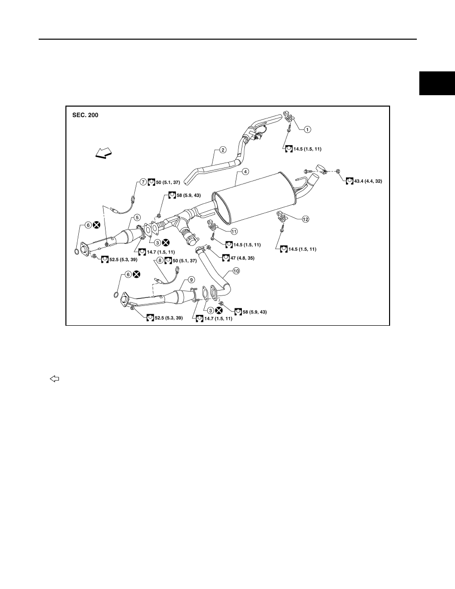
Exploded View
INFOID:0000000003939459
VQ40DE Exhaust System
WBIA0729E
1.
Tailpipe hanger bracket
2.
Tailpipe
3.
Gasket
4.
Main muffler
5.
Right front exhaust tube
6.
Ring gasket
7.
Heated oxygen sensor 2 (bank 2)
8.
Heated oxygen sensor 2 (bank 1)
9.
Left front exhaust tube
10. Center exhaust tube
11. Muffler hanger bracket front
12. Muffler hanger bracket rear
Front
2009 Pathfinder