Nissan Pathfinder (2009 year). Manual - part 373
ROCKER COVER
EM-41
< ON-VEHICLE REPAIR >
[VQ40DE]
C
D
E
F
G
H
I
J
K
L
M
A
EM
N
P
O
ROCKER COVER
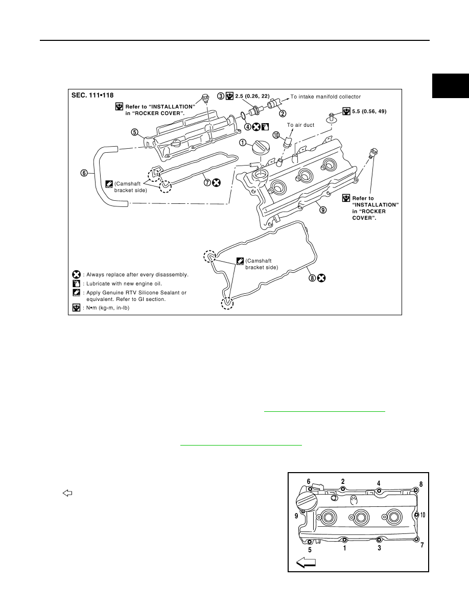
Exploded View
INFOID:0000000003939497
Removal and Installation
INFOID:0000000003939498
REMOVAL (LH)
1.
Remove the engine room cover using power tool. Refer to
EM-24, "Removal and Installation"
.
2.
Separate engine harness removing their brackets from rocker covers.
3.
Remove harness bracket from cylinder head, if necessary.
4.
Remove the ignition coils. Refer to
EM-40, "Removal and Installation"
.
5.
Remove the PCV hoses from rocker covers.
6.
Remove the oil filler cap from rocker cover (LH), if necessary.
7.
Loosen the rocker cover bolts with power tool in reverse order
as shown.
•
: Front
1.
Oil filler cap
2.
PCV hose
3.
PCV valve
4.
O-ring
5.
Rocker cover (RH)
6.
PCV hose
7.
Rocker cover gasket (RH)
8.
Rocker cover gasket (LH)
9.
Rocker cover (LH)
10. PCV hose
PBIC2905E
AWBIA0729ZZ
2009 Pathfinder