Nissan Pathfinder (2009 year). Manual - part 296
EC-382
< COMPONENT DIAGNOSIS >
[VQ40DE]
P2A00, P2A03 A/F SENSOR 1
NG
>> Repair or replace.
4.
CLEAR THE SELF-LEARNING DATA.
With CONSULT-III
1.
Start engine and warm it up to normal operating temperature.
2.
Select “SELF-LEARNING CONT” in “WORK SUPPORT” mode with CONSULT-III.
3.
Clear the self-learning control coefficient by touching “CLEAR”.
4.
Run engine for at least 10 minutes at idle speed.
Is the 1st trip DTC P0171, P0172, P0174 or P0175 detected?
Is it difficult to start engine?
Without CONSULT-III
1.
Start engine and warm it up to normal operating temperature.
2.
Turn ignition switch OFF.
3.
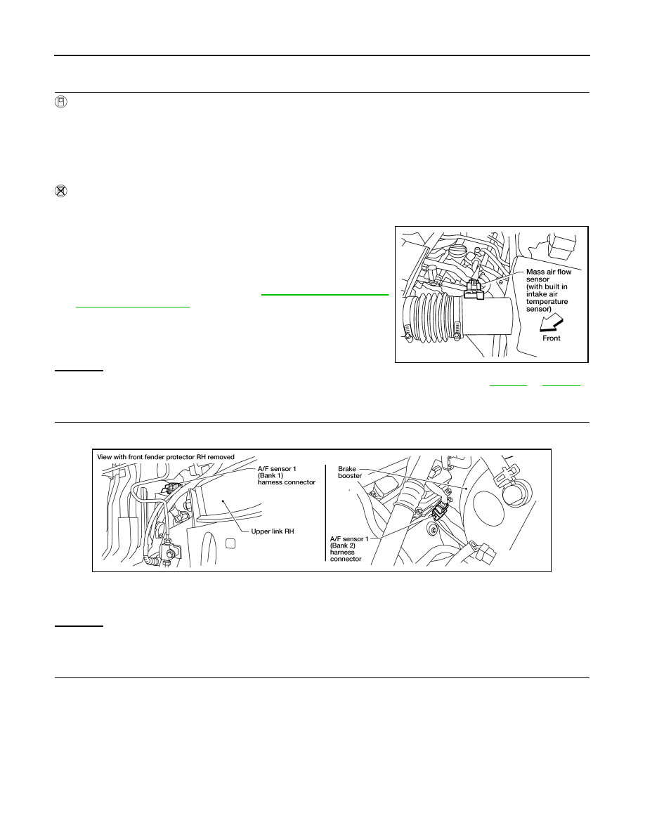
Disconnect mass air flow sensor harness connector.
4.
Restart engine and let it idle for at least 3 seconds.
5.
Stop engine and reconnect mass air flow sensor harness con-
nector.
6.
Make sure DTC P0102 is displayed.
7.
Erase the DTC memory. Refer to
8.
Make sure DTC P0000 is displayed.
9.
Run engine for at least 10 minutes at idle speed.
Is the 1st trip DTC P0171, P0172 or P0174, P0175 detected?
Is it difficult to start engine?
Yes or No
Yes
>> Perform trouble diagnosis for DTC P0171, P0174 or P0172, P0175. Refer to
No
>> GO TO 5.
5.
CHECK HARNESS CONNECTOR
1.
Turn ignition switch OFF.
2.
Disconnect A/F sensor 1 harness connector.
3.
Check harness connector for water.
OK or NG
OK
>> GO TO 6.
NG
>> Repair or replace harness connector.
6.
CHECK A/F SENSOR 1 POWER SUPPLY CIRCUIT
1.
Turn ignition switch ON.
BBIA0541E
Water should not exit.
BBIA0544E
2009 Pathfinder