Nissan Pathfinder (2009 year). Manual - part 284


  Index      Manuals     Nissan Pathfinder (2009 year) - Service and Repair Manual


Search            copyright infringement  


Content      ..     282      283      284      285     ..


Nissan Pathfinder (2009 year). Manual - part 284


EC-286

< COMPONENT DIAGNOSIS >

[VQ40DE]

P0462, P0463 FUEL LEVEL SENSOR

P0462, P0463 FUEL LEVEL SENSOR

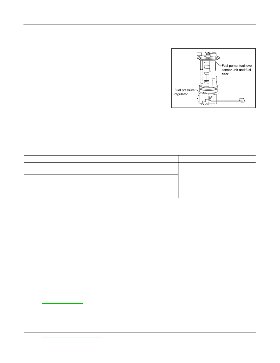
Component Description

INFOID:0000000004297476

The fuel level sensor is mounted in the fuel level sensor unit. The
sensor detects a fuel level in the fuel tank and transmits a signal to
the combination meter. The combination meter sends the fuel level
sensor signal to the ECM through CAN communication line.
It consists of two parts, one is mechanical float and the other is vari-
able resistor. Fuel level sensor output voltage changes depending on
the movement of the fuel mechanical float.

On Board Diagnosis Logic

INFOID:0000000004297477

NOTE:
• If DTC P0462 or P0463 is displayed with DTC UXXXX, first perform the trouble diagnosis for DTC

UXXXX.

• If DTC P0462 or P0463 is displayed with DTC P0607, first perform the trouble diagnosis for DTC

P0607. Refer to 

EC-301, "Description"

.

DTC Confirmation Procedure

INFOID:0000000004297478

NOTE:
If DTC Confirmation Procedure has been previously conducted, always perform the following before conduct-
ing the next step.
1.

Turn ignition switch OFF and wait at least 10 seconds.

2.

Turn ignition switch ON.

3.

Turn ignition switch OFF and wait at least 10 seconds.

TESTING CONDITION:
Before performing the following procedure, confirm that battery voltage is more than 11V at ignition
switch ON.
1.

Turn ignition switch ON and wait at least 5 seconds.

2.

Check 1st trip DTC.

3.

If 1st trip DTC is detected, go to 

EC-286, "Diagnosis Procedure"

.

Diagnosis Procedure

INFOID:0000000004297479

1.

CHECK COMBINATION METER FUNCTION

Refer to 

GI-45, "Work Flow"

.

OK or NG

OK

>> GO TO 2.

NG

>> Go to 

MWI-32, "Component Function Check"

.

2.

CHECK INTERMITTENT INCIDENT

Refer to 

GI-49, "Intermittent Incident"

.

BBIA0529E

DTC No.

Trouble diagnosis name

DTC detecting condition

Possible cause

P0462
0462

Fuel level sensor circuit 
low input

An excessively low voltage from the sensor is 
sent to ECM.

• Harness or connectors

(The CAN communication line is open or 
shorted)

• Harness or connectors

(The sensor circuit is open or shorted)

• Combination meter
• Fuel level sensor

P0463
0463

Fuel level sensor circuit 
high input

An excessively high voltage from the sensor is 
sent to ECM.

2009 Pathfinder

P0462, P0463 FUEL LEVEL SENSOR

EC-287

< COMPONENT DIAGNOSIS >

[VQ40DE]

C

D

E

F

G

H

I

J

K

L

M

A

EC

N

P

O

>> INSPECTION END

2009 Pathfinder

EC-288

< COMPONENT DIAGNOSIS >

[VQ40DE]

P0500 VSS

P0500 VSS

Description

INFOID:0000000004297480

NOTE:
• If DTC P0500 is displayed with DTC UXXXX, first perform the trouble diagnosis for DTC UXXXX.
• If DTC P0500 is displayed with DTC P0607, first perform the trouble diagnosis for DTC P0607. Refer

to 

EC-301, "Description"

.

The vehicle speed signal is sent to the combination meter from the “ABS actuator and electric unit (control
unit)” by CAN communication line. The combination meter then sends a signal to the ECM by CAN communi-
cation line.

On Board Diagnosis Logic

INFOID:0000000004297481

FAIL-SAFE MODE

When the malfunction is detected, ECM enters fail-safe mode.

DTC Confirmation Procedure

INFOID:0000000004297482

CAUTION:

Always drive vehicle at a safe speed.
NOTE:
If DTC Confirmation Procedure has been previously conducted, always perform the following before conduct-
ing the next step.
1.

Turn ignition switch OFF and wait at least 10 seconds.

2.

Turn ignition switch ON.

3.

Turn ignition switch OFF and wait at least 10 seconds.

TESTING CONDITION:
Steps 1 and 2 may be conducted with the drive wheels lifted in the shop or by driving the vehicle. If a
road test is expected to be easier, it is unnecessary to lift the vehicle.

 WITH CONSULT-III

1.

Start engine (VDC switch OFF).

2.

Read “VHCL SPEED SE” in “DATA MONITOR” mode with CONSULT-III. The vehicle speed on CON-
SULT-III should exceed 10 km/h (6 MPH) when rotating wheels with suitable gear position.
If NG, go to 

EC-289, "Diagnosis Procedure"

.

If OK, go to following step.

3.

Select “DATA MONITOR” mode with CONSULT-III.

4.

Warm engine up to normal operating temperature.

5.

Maintain the following conditions for at least 60 consecutive seconds.

DTC No.

Trouble diagnosis name

DTC detecting condition

Possible cause

P0500
0500

Vehicle speed sensor

The almost 0 km/h (0 MPH) signal from 
vehicle speed sensor is sent to ECM even 
when vehicle is being driven.

• Harness or connectors

(The CAN communication line is open or short-
ed)

• Harness or connectors

(The vehicle speed signal circuit is open or 
shorted)

• Wheel sensor
• Combination meter
• ABS actuator and electric unit (control unit) 

Detected item

Engine operating condition in fail-safe mode

Vehicle speed sensor

When the fail-safe system for vehicle speed sensor is activated, the cooling fan operates 
(High) while engine is running.

ENG SPEED

1,700 - 6,000 rpm

COOLAN TEMP/S

More than 70

°

C (158

°

F)

B/FUEL SCHDL

6.3 - 31.8 msec

2009 Pathfinder

P0500 VSS

EC-289

< COMPONENT DIAGNOSIS >

[VQ40DE]

C

D

E

F

G

H

I

J

K

L

M

A

EC

N

P

O

6.

Check 1st trip DTC.

7.

If 1st trip DTC is detected, go to 

EC-289, "Diagnosis Procedure"

.

Overall Function Check

INFOID:0000000004297483

Use this procedure to check the overall function of the vehicle speed sensor circuit. During this check, a 1st
trip DTC might not be confirmed.

 WITH GST

1.

Lift up drive wheels.

2.

Start engine.

3.

Read vehicle speed sensor signal in Service $01 with GST.
The vehicle speed sensor on GST should be able to exceed 10 km/h (6 MPH) when rotating wheels with
suitable gear position.

4.

If NG, go to 

EC-289, "Diagnosis Procedure"

.

Diagnosis Procedure

INFOID:0000000004297484

1.

CHECK DTC WITH “ABS ACTUATOR AND ELECTRIC UNIT (CONTROL UNIT)”

Refer to 

BRC-8, "Work Flow"

 or 

BRC-137, "Work Flow"

.

OK or NG

OK

>> GO TO 2.

NG

>> Repair or replace.

2.

CHECK COMBINATION METER FUNCTION

Refer to 

GI-45, "Work Flow"

.

>> INSPECTION END

Selector lever

Except P or N position

PW/ST SIGNAL

OFF

2009 Pathfinder

EC-290

< COMPONENT DIAGNOSIS >

[VQ40DE]

P0506 ISC SYSTEM

P0506 ISC SYSTEM

Description

INFOID:0000000004297485

NOTE:
If DTC P0506 is displayed with other DTC, first perform the trouble diagnosis for the other DTC.
The ECM controls the engine idle speed to a specified level through the fine adjustment of the air, which is let
into the intake manifold, by operating the electric throttle control actuator. The operating of the throttle valve is
varied to allow for optimum control of the engine idling speed. The crankshaft position sensor (POS) detects
the actual engine speed and sends a signal to the ECM.
The ECM controls the electric throttle control actuator so that the engine speed coincides with the target value
memorized in the ECM. The target engine speed is the lowest speed at which the engine can operate steadily.
The optimum value stored in the ECM is determined by taking into consideration various engine conditions,
such as during warming up, deceleration, and engine load (air conditioner, power steering and cooling fan
operation, etc.). 

On Board Diagnosis Logic

INFOID:0000000004297486

DTC Confirmation Procedure

INFOID:0000000004297487

NOTE:
• If the target idle speed is out of the specified value, perform, 

EC-25, "Idle Air Volume Learning"

,

before conducting DTC Confirmation Procedure. For the target idle speed, refer to the 

EC-488

.

• If DTC Confirmation Procedure has been previously conducted, always perform the following before con-

ducting the next step.

1.

Turn ignition switch OFF and wait at least 10 seconds.

2.

Turn ignition switch ON.

3.

Turn ignition switch OFF and wait at least 10 seconds.

TESTING CONDITION:
• Before performing the following procedure,confirm that battery voltage is more than 11V at idle.
• Always perform the test at a temperature above 

10

°

C(14

°

F).

1.

Start engine and warm it up to normal operating temperature.

2.

Turn ignition switch OFF and wait at least 10 seconds.

3.

Turn ignition switch ON.

4.

Turn ignition switch OFF and wait at least 10 seconds.

5.

Start engine and run it for at least 1 minute at idle speed.

6.

Check 1st trip DTC.

7.

If 1st trip DTC is detected, go to 

EC-290, "Diagnosis Procedure"

.

Diagnosis Procedure

INFOID:0000000004297488

1.

CHECK INTAKE AIR LEAK

1.

Start engine and let it idle.

2.

Listen for an intake air leak after the mass air flow sensor.

OK or NG

OK

>> GO TO 2.

NG

>> Discover air leak location and repair.

2.

REPLACE ECM

1.

Stop engine.

2.

Replace ECM.

3.

Perform initialization of NVIS (NATS) system and registration of all NVIS (NATS) ignition key IDs. Refer to

SEC-8, "ADDITIONAL SERVICE WHEN REPLACING CONTROL UNIT : Special Repair Requirement"

DTC No.

Trouble diagnosis name

DTC detecting condition

Possible cause

P0506
0506

Idle speed control sys-
tem RPM lower than ex-
pected

The idle speed is less than the target idle speed 
by 100 rpm or more.

• Electric throttle control actuator
• Intake air leak

2009 Pathfinder

EC-292

< COMPONENT DIAGNOSIS >

[VQ40DE]

P0507 ISC SYSTEM

P0507 ISC SYSTEM

Description

INFOID:0000000004297489

NOTE:
If DTC P0507 is displayed with other DTC, first perform the trouble diagnosis for the other DTC.
The ECM controls the engine idle speed to a specified level through the fine adjustment of the air, which is let
into the intake manifold, by operating the electric throttle control actuator. The operating of the throttle valve is
varied to allow for optimum control of the engine idling speed. The crankshaft position sensor (POS) detects
the actual engine speed and sends a signal to the ECM.
The ECM controls the electric throttle control actuator so that the engine speed coincides with the target value
memorized in the ECM. The target engine speed is the lowest speed at which the engine can operate steadily.
The optimum value stored in the ECM is determined by taking into consideration various engine conditions,
such as during warming up, deceleration and engine load (air conditioner, power steering and cooling fan
operation, etc.). 

On Board Diagnosis Logic

INFOID:0000000004297490

DTC Confirmation Procedure

INFOID:0000000004297491

NOTE:
• If the target idle speed is out of the specified value, perform, 

EC-25, "Idle Air Volume Learning"

,

before conducting DTC Confirmation Procedure. For the target idle speed, refer to the 

EC-488

.

• If DTC Confirmation Procedure has been previously conducted, always perform the following before con-

ducting the next step.

1.

Turn ignition switch OFF and wait at least 10 seconds.

2.

Turn ignition switch ON.

3.

Turn ignition switch OFF and wait at least 10 seconds.

TESTING CONDITION:
• Before performing the following procedure, confirm that battery voltage is more than 11V at idle.
• Always perform the test at a temperature above 

10

°

C(14

°

F).

1.

Start engine and warm it up to normal operating temperature.

2.

Turn ignition switch OFF and wait at least 10 seconds.

3.

Turn ignition switch ON.

4.

Turn ignition switch OFF and wait at least 10 seconds.

5.

Start engine and run it for at least 1 minute at idle speed.

6.

Check 1st trip DTC.

7.

If 1st trip DTC is detected, go to 

EC-292, "Diagnosis Procedure"

.

Diagnosis Procedure

INFOID:0000000004297492

1.

CHECK PCV HOSE CONNECTION

Confirm that PCV hose is connected correctly.

OK or NG

OK

>> GO TO 2.

NG

>> Repair or replace.

2.

CHECK INTAKE AIR LEAK

1.

Start engine and let it idle.

2.

Listen for an intake air leak after the mass air flow sensor.

OK or NG

OK

>> GO TO 3.

NG

>> Discover air leak location and repair.

DTC No.

Trouble diagnosis name

DTC detecting condition

Possible cause

P0507
0507

Idle speed control sys-
tem RPM higher than 
expected

The idle speed is more than the target idle 
speed by 200 rpm or more.

• Electric throttle control actuator
• Intake air leak
• PCV system

2009 Pathfinder

P0507 ISC SYSTEM

EC-293

< COMPONENT DIAGNOSIS >

[VQ40DE]

C

D

E

F

G

H

I

J

K

L

M

A

EC

N

P

O

3.

REPLACE ECM

1.

Stop engine.

2.

Replace ECM.

3.

Perform initialization of NVIS(NATS) system and registration of all NVIS(NATS) ignition key IDs. Refer to

SEC-8, "ADDITIONAL SERVICE WHEN REPLACING CONTROL UNIT : Special Repair Requirement"

(with Intelligent Key system) or 

SEC-124, "ADDITIONAL SERVICE WHEN REPLACING CONTROL UNIT

: Special Repair Requirement"

 (without Intelligent Key System).

4.

Perform 

EC-25, "VIN Registration"

.

5.

Perform 

EC-25, "Accelerator Pedal Released Position Learning"

.

6.

Perform 

EC-25, "Throttle Valve Closed Position Learning"

.

7.

Perform 

EC-25, "Idle Air Volume Learning"

.

>> INSPECTION END

2009 Pathfinder


Content      ..     282      283      284      285     ..