Nissan Pathfinder (2009 year). Manual - part 174


  Index      Manuals     Nissan Pathfinder (2009 year) - Service and Repair Manual


Search            copyright infringement  


Content      ..     172      173      174      175     ..


Nissan Pathfinder (2009 year). Manual - part 174


FRONT DOOR LOCK

DLK-201

< ON-VEHICLE REPAIR >

[WITH INTELLIGENT KEY SYSTEM]

C

D

E

F

G

H

I

J

L

M

A

B

DLK

N

O

P

4.

If equipped, separate the door key cylinder rod from the door key cylinder assembly.

5.

Disconnect the intelligent key electrical connectors.

6.

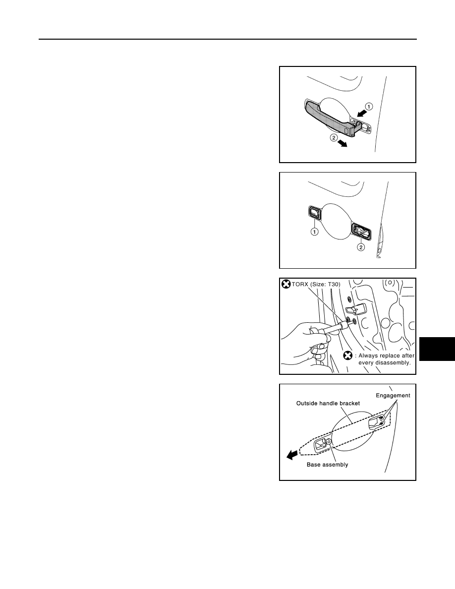
While pulling outside handle (1), slide toward rear of vehicle (2)
to remove outside handle.

7.

Remove the front gasket (1) and rear gasket (2).

8.

Remove the TORX bolts (T30), remove the door lock assembly.

9.

While pulling outside handle bracket, slide toward rear of vehicle
to remove outside handle bracket and door lock assembly as
shown.

10. Disconnect the door lock actuator electrical connector.

ALKIA0923ZZ

ALKIA0924ZZ

PIIA1090E

PIIA3558E

2009 Pathfinder

DLK-202

< ON-VEHICLE REPAIR >

[WITH INTELLIGENT KEY SYSTEM]

FRONT DOOR LOCK

11. Separate the outside handle cable connection from the outside

handle bracket.

INSTALLATION

Installation is in the reverse order of removal.

CAUTION:

To install the key cylinder rod, be sure to rotate the key cylinder rod holder until a click is felt.

Disassembly and Assembly

INFOID:0000000003938286

DOOR KEY CYLINDER ASSEMBLY

Release the key cylinder escutcheon pawls to remove the door key cylinder.

PIIA5059E

1.

Door key cylinder assembly

2.

Door key cylinder escutcheon

3.

Door key cylinder

Pawl

WIIA1057E

2009 Pathfinder

REAR DOOR LOCK

DLK-203

< ON-VEHICLE REPAIR >

[WITH INTELLIGENT KEY SYSTEM]

C

D

E

F

G

H

I

J

L

M

A

B

DLK

N

O

P

REAR DOOR LOCK

Component Structure

INFOID:0000000003938287

Removal and Installation

INFOID:0000000003938288

REMOVAL

1.

Remove the rear door window regulator. Refer to 

GW-19, "Rear Door Glass Regulator"

.

2.

Remove door grommets, and remove outside handle nuts from the hole.

3.

Remove outside handle.

4.

Disconnect the outside handle cable connection.

5.

Remove the inside door handle.

6.

Disconnect the door lock and inside door handle cables from the inside door handle.

7.

Disconnect the door lock actuator connector and remove the assembly.

INSTALLATION

Installation is in the reverse order of removal.

1.

Outside door handle

2.

Rear door striker

3.

Rear door lock assembly

4.

Outside door handle cable

5.

Inside door handle cable

6.

Inside door handle assembly

7.

Door lock cable

Vehicle front

WIIA0737E

2009 Pathfinder

DLK-204

< ON-VEHICLE REPAIR >

[WITH INTELLIGENT KEY SYSTEM]

BACK DOOR LOCK

BACK DOOR LOCK

Component Structure

INFOID:0000000003938289

1.

Glass hatch latch assembly

2.

Back door control assembly

3.

Back door striker 

4.

Back door latch assembly

5.

Back door release button

6.

Back door finisher

7.

Key button

8.

Glass hatch release handle 

9.

Glass hatch release cable

Front

AWKIA1438GB

2009 Pathfinder

DIAGNOSIS AND REPAIR WORKFLOW

DLK-205

< BASIC INSPECTION >

[WITHOUT INTELLIGENT KEY SYSTEM]

C

D

E

F

G

H

I

J

L

M

A

B

DLK

N

O

P

BASIC INSPECTION

DIAGNOSIS AND REPAIR WORKFLOW

Work Flow

INFOID:0000000003938290

OVERALL SEQUENCE

DETAILED FLOW

JMKIA2270GB

2009 Pathfinder

DLK-206

< BASIC INSPECTION >

[WITHOUT INTELLIGENT KEY SYSTEM]

DIAGNOSIS AND REPAIR WORKFLOW

1.

GET INFORMATION FOR SYMPTOM

Get the detailed information from the customer about the symptom (the condition and the environment when
the incident/malfunction occurred).

>> GO TO 2

2.

CHECK DTC

1.

Check DTC.

2.

Perform the following procedure if DTC is displayed.

-

Record DTC and freeze frame data (Print them out with CONSULT-III.)

-

Erase DTC.

-

Study the relationship between the cause detected by DTC and the symptom described by the customer.

3.

Check related service bulletins for information.

Is any symptom described and any DTC detected?

Symptom is described, DTC is displayed>>GO TO 3
Symptom is described, DTC is not displayed>>GO TO 4
Symptom is not described, DTC is displayed>>GO TO 5

3.

CONFIRM THE SYMPTOM

Confirm the symptom described by the customer.
Connect CONSULT-III to the vehicle in “DATA MONITOR” mode and check real time diagnosis results.
Verify relation between the symptom and the condition when the symptom is detected.

>> GO TO 5

4.

CONFIRM THE SYMPTOM

Confirm the symptom described by the customer.
Connect CONSULT-III to the vehicle in “DATA MONITOR ” mode and check real time diagnosis results.
Verify relation between the symptom and the condition when the symptom is detected.

>> GO TO 6

5.

PERFORM DTC CONFIRMATION PROCEDURE

Perform DTC Confirmation Procedure for the displayed DTC, and then check that DTC is detected again.
At this time, always connect CONSULT-III to the vehicle, and check diagnostic results in real time.
If two or more DTCs are detected, refer to 

DLK-299, "DTC Inspection Priority Chart"

 and determine trouble

diagnosis order.
NOTE:
• Freeze frame data is useful if the DTC is not detected.
• Perform Component Function Check if DTC Confirmation Procedure is not included in Service Manual. This

simplified check procedure is an effective alternative though DTC cannot be detected during this check.
If the result of Component Function Check is NG, it is the same as the detection of DTC by DTC Confirma-
tion Procedure.

Is DTC detected?

YES

>> GO TO 7

NO

>> Refer to 

GI-49, "Intermittent Incident"

.

6.

DETECT MALFUNCTIONING SYSTEM BY SYMPTOM TABLE

Detect malfunctioning system according to SYMPTOM DIAGNOSIS based on the confirmed symptom in step
4, and determine the trouble diagnosis order based on possible causes and symptom.

>> GO TO 7

7.

DETECT MALFUNCTIONING PART BY DIAGNOSTIC PROCEDURE

Inspect according to Diagnostic Procedure of the system.
NOTE:

2009 Pathfinder

DIAGNOSIS AND REPAIR WORKFLOW

DLK-207

< BASIC INSPECTION >

[WITHOUT INTELLIGENT KEY SYSTEM]

C

D

E

F

G

H

I

J

L

M

A

B

DLK

N

O

P

The Diagnostic Procedure described based on open circuit inspection. A short circuit inspection is also
required for the circuit check in the Diagnostic Procedure.
Is malfunctioning part detected?

YES

>> GO TO 8

NO

>> Check voltage of related BCM terminals using CONSULT-III.

8.

REPAIR OR REPLACE THE MALFUNCTIONING PART

1.

Repair or replace the malfunctioning part.

2.

Reconnect parts or connectors disconnected during Diagnostic Procedure again after repair and replace-
ment.

3.

Check DTC. If DTC is displayed, erase it.

>> GO TO 9

9.

FINAL CHECK

When DTC was detected in step 2, perform DTC Confirmation Procedure or Component Function Check
again, and then check that the malfunction have been repaired securely.
When symptom was described from the customer, refer to confirmed symptom in step 3 or 4, and check that
the symptom is not detected.
Is the inspection result normal?

NO (DTC is detected)>>GO TO 7
NO (Symptom remains)>>GO TO 6
YES

>> Inspection End.

2009 Pathfinder

DLK-208

< BASIC INSPECTION >

[WITHOUT INTELLIGENT KEY SYSTEM]

INSPECTION AND ADJUSTMENT

INSPECTION AND ADJUSTMENT

ADDITIONAL SERVICE WHEN REPLACING CONTROL UNIT

ADDITIONAL SERVICE WHEN REPLACING CONTROL UNIT : Description

INFOID:0000000003938291

Perform the system initialization when replacing BCM, replacing a keyfob or registering an additional keyfob.

ADDITIONAL SERVICE WHEN REPLACING CONTROL UNIT : Special Repair Re-
quirement

INFOID:0000000003938292

Refer to the CONSULT-III Operation Manual for the initialization procedure.

2009 Pathfinder


Content      ..     172      173      174      175     ..