Nissan Pathfinder (2009 year). Manual - part 23
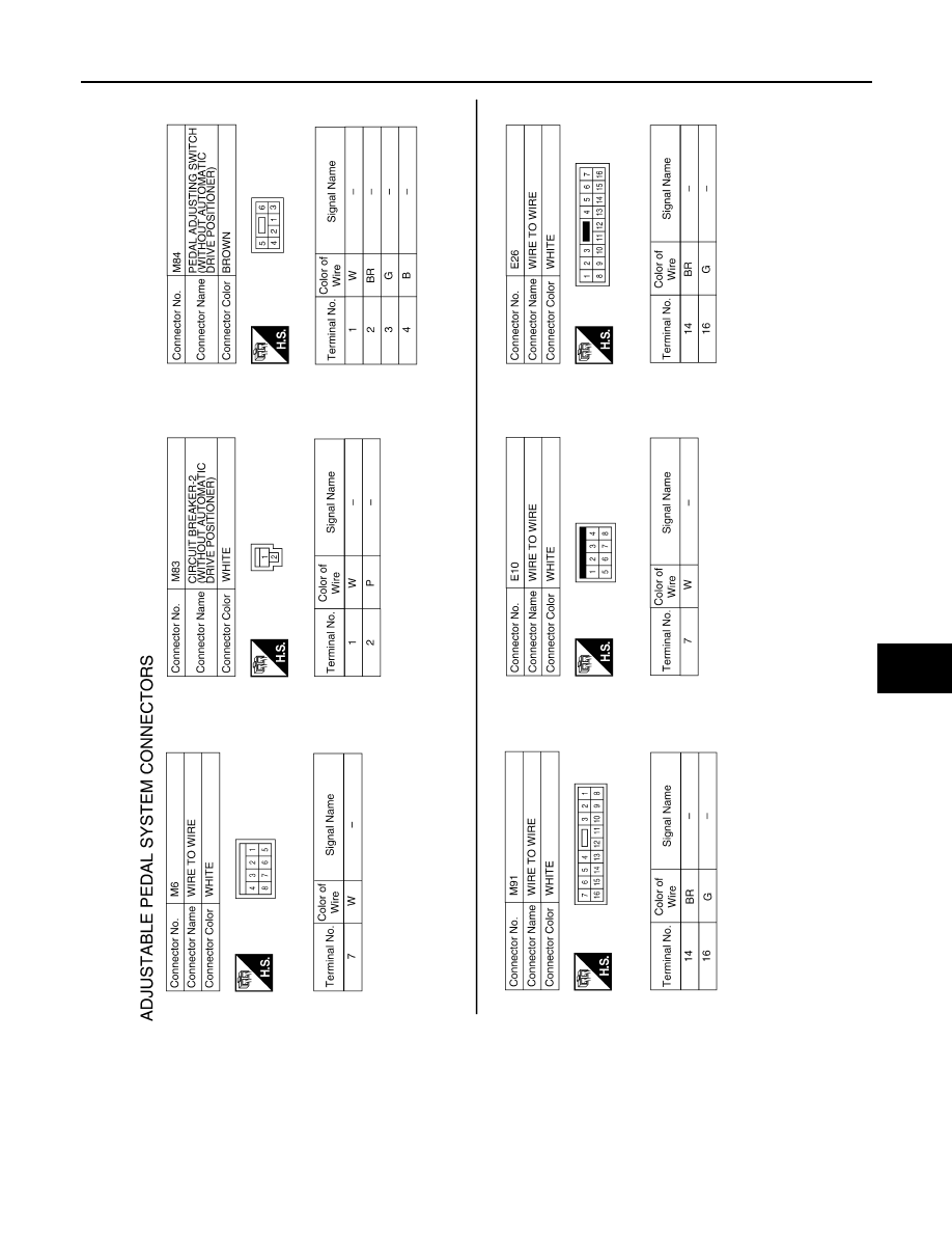
ADJUSTABLE PEDAL SYSTEM
AP-9
< COMPONENT DIAGNOSIS >
C
D
E
F
G
H
I
K
L
M
A
B
AP
N
O
P
ABJIA0002GB
2009 Pathfinder
|
|
|
ADJUSTABLE PEDAL SYSTEM AP-9 < COMPONENT DIAGNOSIS > C D E F G H I K L M A B AP N O P ABJIA0002GB 2009 Pathfinder |