Nissan Pathfinder (2009 year). Manual - part 8
LIFTING SWITCH (REAR)
ADP-51
< COMPONENT DIAGNOSIS >
C
D
E
F
G
H
I
K
L
M
A
B
ADP
N
O
P
Is the inspection result normal?
YES
>> GO TO 3
NO
>> Repair or replace harness.
3.
CHECK DRIVER SEAT CONTROL UNIT OUTPUT
1.
Connect the driver seat control unit.
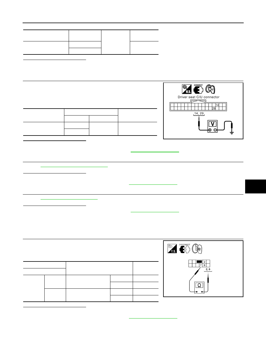
2.
Turn ignition switch ON.
3.
Check voltage between driver seat control unit harness connec-
tor and ground.
Is the inspection result normal?
YES
>> GO TO 4
NO
>> Replace driver seat control unit. Refer to
4.
CHECK LIFTING SWITCH (REAR)
ADP-51, "Component Inspection"
.
Is the inspection result normal?
YES
>> GO TO 5
NO
>> Replace power seat switch LH. Refer to
.
5.
CHECK INTERMITTENT INCIDENT
GI-49, "Intermittent Incident"
.
Is the inspection result normal?
YES
>> Replace driver seat control unit. Refer to
NO
>> Repair or replace the malfunctioning part.
Component Inspection
INFOID:0000000003935524
1.
CHECK LIFTING SWITCH (REAR)
1.
Turn ignition switch OFF.
2.
Disconnect power seat switch LH.
3.
Check continuity between power seat switch LH terminals.
Is the inspection result normal?
YES
>> Inspection End.
NO
>> Replace power seat switch LH. Refer to
.
Driver seat control unit
connector
Terminal
Ground
Continuity
B202 (A)
14
No
29
Driver seat control unit
connector
Terminals
Voltage (V)
(Approx.)
(+)
(–)
B202
14
Ground
Battery voltage
29
PIIA4586E
Terminal
Condition
Continuity
Power seat switch LH
7
2
Lifting switch rear (up)
Operate
Yes
Release
No
6
Lifting switch rear (down)
Operate
Yes
Release
No
ALJIA0315ZZ
2009 Pathfinder