Nissan Pathfinder (2007 year). Manual - part 423
TROUBLE DIAGNOSIS FOR SYMPTOMS
TF-265
[TX15B]
C
E
F
G
H
I
J
K
L
M
A
B
TF
2007 Pathfinder
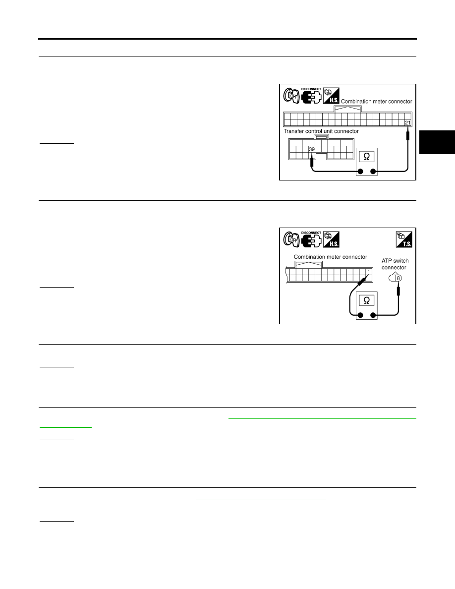
6.
CHECK HARNESS BETWEEN TRANSFER CONTROL UNIT AND COMBINATION METER
1.
Turn ignition switch “OFF”. (Stay for at least 5 seconds.)
2.
Disconnect transfer control unit harness connector and combination meter harness connector.
3.
Check continuity between transfer control unit harness connec-
tor M153 terminal 39 and combination meter harness connector
M24 terminal 21.
Also check harness for short to ground and short to power.
OK or NG
OK >> GO
TO
7.
NG
>> Repair or replace damaged parts.
7.
CHECK HARNESS BETWEEN COMBINATION METER AND ATP SWITCH
1.
Turn ignition switch “OFF”. (Stay for at least 5 seconds.)
2.
Disconnect ATP switch harness connector.
3.
Check continuity between combination meter harness connector
M24 terminal 1 and ATP switch harness connector F55 terminal
8.
Also check harness for short to ground and short to power.
OK or NG
OK >> GO
TO
8.
NG
>> Repair or replace damaged parts.
8.
SYMPTOM CHECK
Check again.
OK or NG
OK
>> Inspection End.
NG
>> GO TO 9.
9.
CHECK TRANSFER CONTROL UNIT
Check transfer control unit input/output signal. Refer to
TF-211, "Transfer Control Unit Input/Output Signal Ref-
.
OK or NG
OK
>> GO TO 10.
NG
>> Check transfer control unit pin terminals for damage or loose connection with harness connector.
If any items are damaged, repair or replace damaged parts.
10.
CHECK TRANSFER INNER PARTS
1.
Disassemble transfer assembly. Refer to
TF-278, "Disassembly and Assembly"
2.
Check transfer inner parts.
OK or NG
OK
>> Inspection End.
NG
>> Repair or replace damaged parts.
Continuity should exist.
SDIA2825E
Continuity should exist.
SDIA2833E