Nissan Pathfinder (2007 year). Manual - part 399


  Index      Manuals     Nissan Pathfinder (2007 year) - Service and Repair Manual


Search            copyright infringement  


Content      ..     397      398      399      400     ..


Nissan Pathfinder (2007 year). Manual - part 399


TROUBLE DIAGNOSIS FOR SYSTEM

TF-73

[ATX14B]

C

E

F

G

H

I

J

K

L

M

A

B

TF

2007 Pathfinder

DIAGNOSTIC PROCEDURE

1. 

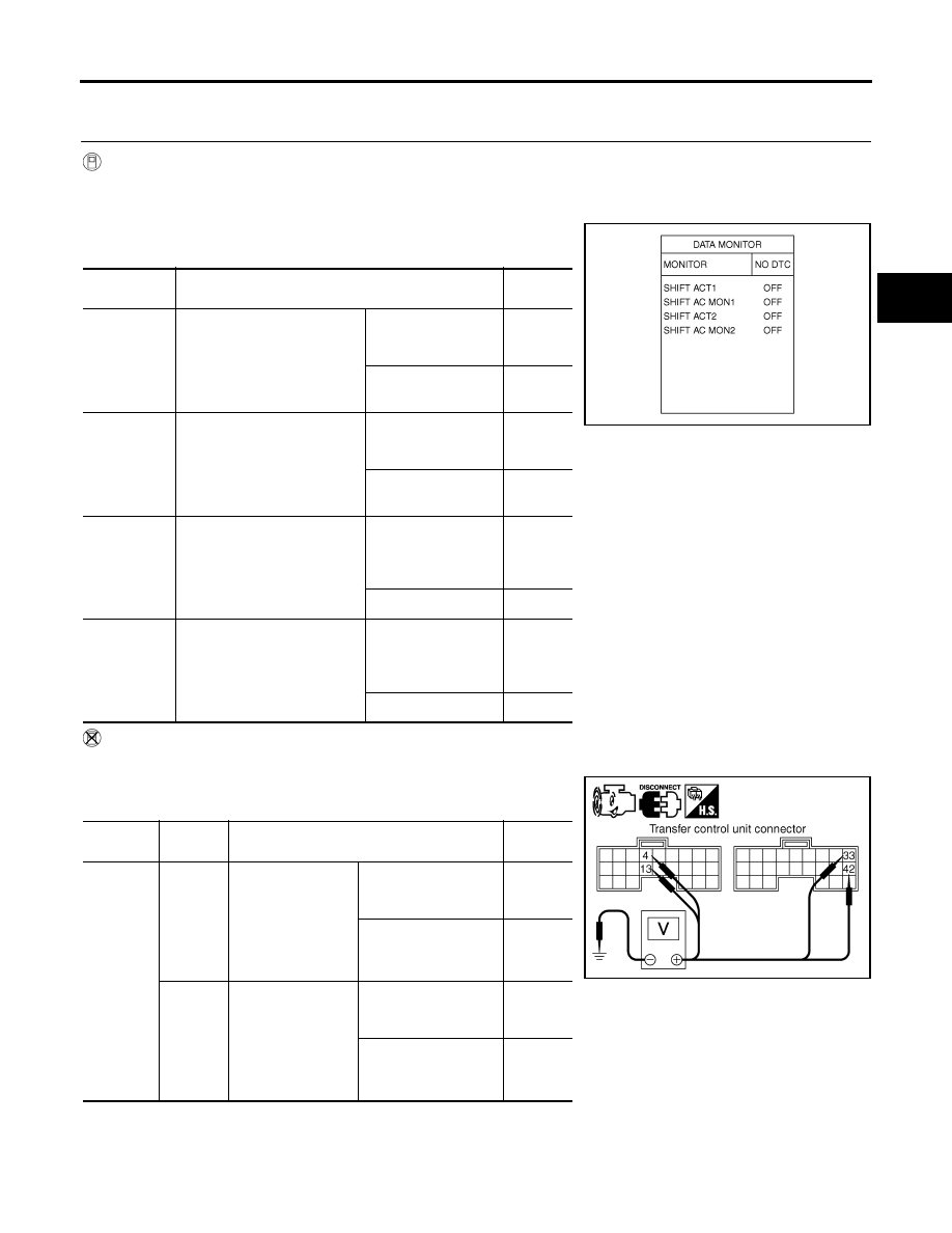
CHECK ACTUATOR MOTOR SIGNAL

 With CONSULT-II

1.

Start engine.

2.

Select “DATA MONITOR” mode for “ALL MODE AWD/4WD” with CONSULT-II.

3.

Read out the value of “SHIFT ACT1”, “SHIFT AC MON1”,
“SHIFT ACT2” and “SHIFT AC MON2”.

 Without CONSULT-II

1.

Start engine.

2.

Check voltage between transfer control unit harness connector
terminal and ground.

Monitored 

item

Condition

Display 

value

SHIFT ACT1

Vehicle stopped

Engine running

A/T selector lever “N” posi-
tion

Brake pedal depressed

4WD shift switch: 4H 
to 4LO (“Wait” func-
tion is operating.)

ON

Except the above

OFF

SHIFT AC 
MON1

Vehicle stopped

Engine running

A/T selector lever “N” posi-
tion

Brake pedal depressed

4WD shift switch: 4H 
to 4LO (“Wait” func-
tion is operating.)

ON

Except the above

OFF

SHIFT ACT2

Vehicle stopped

Engine running

A/T selector lever “N” posi-
tion

Brake pedal depressed

4WD shift switch: 
4LO to 4H (“Wait” 
function is operat-
ing.)

ON

Except the above

OFF

SHIFT AC 
MON2

Vehicle stopped

Engine running

A/T selector lever “N” posi-
tion

Brake pedal depressed

4WD shift switch: 
4LO to 4H (“Wait” 
function is operat-
ing.)

ON

Except the above

OFF

Connector

Terminal

Condition

Voltage 

(Approx.)

M152

4 - 

Ground

Vehicle stopped

Engine running

A/T selector lever 
“N” position

Brake pedal 
depressed

4WD shift switch: 4H 
to 4LO (“Wait” function 
is operating.)

Battery 
voltage

Except the above

0V

13 - 

Ground

Vehicle stopped

Engine running

A/T selector lever 
“N” position

Brake pedal 
depressed

4WD shift switch: 4LO 
to 4H (“Wait” function 
is operating.)

Battery 
voltage

Except the above

0V

PDIA0223E

SDIA2705E

TF-74

[ATX14B]

TROUBLE DIAGNOSIS FOR SYSTEM

2007 Pathfinder

OK or NG

OK 

>> GO TO 7.

NG

>> GO TO 2.

2. 

CHECK ACTUATOR MOTOR POWER SUPPLY CIRCUIT

1.

Turn ignition switch “OFF”.  (Stay for at least 5 seconds.)

2.

Remove transfer shift high relay and transfer shift low relay.

3.

Check voltage between transfer shift high relay harness connec-
tor E46 terminal 5, transfer shift low relay harness connector
E47 terminal 5 and ground.

4.

Turn ignition switch “ON”. (Do not start engine.)

5.

Check voltage between transfer shift high relay harness connec-
tor E46 terminal 5, transfer shift low relay harness connector
E47 terminal 5 and ground.

OK or NG

OK

>> GO TO 3.

NG

>> Check the following. If any items are damaged, repair or 

replace damaged parts.

20A fuse [No. 58, located in the fuse block (J/B)]. Refer to 

PG-4, "POWER SUPPLY ROUTING

CIRCUIT"

 .

Harness for short or open between battery, transfer shift high harness connector terminal 5 and
transfer shift low harness connector terminal 5.

M153

33 - 

Ground

Vehicle stopped

Engine running

A/T selector lever 
“N” position

Brake pedal 
depressed

4WD shift switch: 4H 
to 4LO (“Wait” function 
is operating.)

Battery 
voltage

Except the above

0V

42 - 

Ground

Vehicle stopped

Engine running

A/T selector lever 
“N” position

Brake pedal 
depressed

4WD shift switch: 4LO 
to 4H (“Wait” function 
is operating.)

Battery 
voltage

Except the above

0V

Connector

Terminal

Condition

Voltage 

(Approx.)

Connector

Terminal

Voltage (Approx.)

E46

5 - Ground

Battery voltage

E47

5 - Ground

SDIA2707E

Connector

Terminal

Voltage (Approx.)

E46

5 - Ground

Battery voltage

E47

5 - Ground

SDIA2706E

TROUBLE DIAGNOSIS FOR SYSTEM

TF-75

[ATX14B]

C

E

F

G

H

I

J

K

L

M

A

B

TF

2007 Pathfinder

3. 

CHECK ACTUATOR MOTOR GROUND CIRCUIT

1.

Turn ignition switch “OFF”.  (Stay for at least 5 seconds.)

2.

Remove transfer shift high relay and transfer shift low relay.  Refer to 

TF-24, "Location of Electrical Parts"

 .

3.

Check continuity between transfer shift high relay harness con-
nector E46 terminals 1 and 4, and transfer shift low relay har-
ness connector E47 terminals 1 and 4 and ground.

Also check harness for short to power.

OK or NG

OK

>> GO TO 4.

NG

>> Repair open circuit or short to power in harness or con-

nectors.

4. 

CHECK TRANSFER SHIFT RELAYS

1.

Turn ignition switch “OFF”.

2.

Remove transfer shift high relay and transfer shift low relay. Refer to 

TF-24, "Location of Electrical Parts"

 .

3.

Apply 12V direct current between transfer shift relay terminals 1
and 2.

4.

Check continuity between relay terminals 3 and 4, 3 and 5.

OK or NG

OK

>> GO TO 5.

NG

>> Replace the transfer shut off relay.  Refer to 

TF-24, "Location of Electrical Parts"

 .

Continuity should exist.

SDIA2708E

Terminal

Condition

Continuity

3 - 4

12V direct current supply between terminals 1 and 2

No

OFF

Yes

3 - 5

12V direct current supply between terminals 1 and 2

Yes

OFF

No

LDIA0099E

TF-76

[ATX14B]

TROUBLE DIAGNOSIS FOR SYSTEM

2007 Pathfinder

5. 

CHECK HARNESS BETWEEN TRANSFER CONTROL UNIT AND TRANSFER SHIFT RELAY

1.

Turn ignition switch “OFF”.  (Stay for at least 5 seconds.)

2.

Disconnect transfer control unit harness connector and the transfer control device (actuator motor) har-
ness connector.

3.

Remove transfer shift high relay and transfer shift low relay.

4.

Check continuity between the following terminals.

Transfer control unit harness connector M152 terminal 4 and
transfer shift high relay harness connector E46 terminal 2.

Transfer control unit harness connector M152 terminal 13 and
transfer shift low relay harness connector E47 terminal 2.

Transfer control unit harness connector M153 terminal 33 and
transfer shift high relay harness connector E46 terminal 3.

Transfer control unit harness connector M153 terminal 42 and
transfer shift low relay harness connector E47 terminal 3.

Also check harness for short to ground and short to power.

OK or NG

OK

>> GO TO 6.

NG

>> Repair or replace damaged parts.

6. 

CHECK HARNESS BETWEEN TRANSFER CONTROL UNIT AND ACTUATOR MOTOR

1.

Turn ignition switch “OFF”. (Stay for at least 5 seconds.)

2.

Disconnect transfer control unit harness connector and the transfer control device (actuator motor) har-
ness connector.

3.

Check continuity between the following terminals.

Transfer control unit harness connector M153 terminal 33 and
transfer control device (actuator motor) harness connector F58
terminal 21.

Transfer control unit harness connector M153 terminal 42 and
transfer control device (actuator motor) harness connector F58
terminal 24.

Also check harness for short to ground and short to power.

OK or NG

OK

>> GO TO 7.

NG

>> Repair or replace damaged parts.

SDIA2711E

Continuity should exist.

SDIA2712E

Continuity should exist.

SDIA2710E

TROUBLE DIAGNOSIS FOR SYSTEM

TF-77

[ATX14B]

C

E

F

G

H

I

J

K

L

M

A

B

TF

2007 Pathfinder

7. 

CHECK ACTUATOR MOTOR

1.

Remove transfer control device. Refer to 

TF-138, "Removal and Installation"

 .

2.

Check operation by applying battery voltage to transfer control
device (actuator motor) terminals 21 and 24.

CAUTION:

Do not operate actuator motor for more than 1 second.

Change the actuator motor position to “HIGH” when
installing.

Be careful not to overheat the harness.

3.

Check resistance between transfer control device (actuator
motor) terminals 21 and 24.

OK or NG

OK

>> GO TO 8.

NG

>> Replace transfer control device (actuator motor).  Refer

to 

TF-138, "Removal and Installation"

 .

8. 

CHECK TRANSFER CONTROL UNIT

Check transfer control unit input/output signal. Refer to 

TF-37, "Transfer Control Unit Input/Output Signal Ref-

erence Values"

 .

OK or NG

OK

>> GO TO 9.

NG

>> Check transfer control unit pin terminals for damage or loose connection with harness connector.

If any items are damaged, repair or replace damaged parts.

9. 

CHECK DTC

Perform the self-diagnosis, after driving a vehicle for a while.

OK or NG

OK

>> Inspection End.

NG

>> Replace transfer control unit. Refer to 

TF-132, "Removal and Installation"

 .

Terminal

Actuator motor

21 (Battery voltage) - 24 (Ground)

Clockwise rotate

24 (Battery voltage) - 21 (Ground)

Counterclockwise rotate

21 - 24

: Approx. 0.2 

WDIA0224E

SDIA3252E

TF-78

[ATX14B]

TROUBLE DIAGNOSIS FOR SYSTEM

2007 Pathfinder

COMPONENT INSPECTION
Transfer Shift Relay

1.

Turn ignition switch “OFF”.  (Stay for at least 5 seconds.)

2.

Remove transfer shift high relay and transfer shift low relay. Refer to 

TF-24, "Location of Electrical Parts"

 .

3.

Apply 12V direct current between transfer shift relay terminals 1
and 2.

4.

Check continuity between relay terminals 3 and 4, 3 and 5.

5.

If NG, replace transfer shift relay.

Transfer Control Device

1.

Remove transfer control device. Refer to 

TF-138, "Removal and Installation"

 .

2.

Check operation by applying battery voltage to transfer control
device (actuator motor) terminals 21 and 24.

CAUTION:

Do not operate actuator motor for more than 1 second.

Change the actuator motor position to “HIGH” when
installing.

Be careful not to overheat the harness.

3.

Check resistance between transfer control device (actuator
motor) terminals 21 and 24.

4.

If NG, replace transfer control device (actuator motor).  Refer to

TF-138, "Removal and Installation"

 .

Terminal

Condition

Continuity

3 - 4

12V direct current supply between terminals 1 and 2

Yes

OFF

No

3 - 5

12V direct current supply between terminals 1 and 2

Yes

OFF

No

LDIA0099E

Terminal

Actuator motor

21 (Battery voltage) - 24 (Ground)

Clockwise rotate

24 (Battery voltage) - 21 (Ground)

Counterclockwise rotate

21 - 24

: Approx. 0.2 

WDIA0224E

SDIA3252E

TROUBLE DIAGNOSIS FOR SYSTEM

TF-79

[ATX14B]

C

E

F

G

H

I

J

K

L

M

A

B

TF

2007 Pathfinder

Actuator Position Switch

EDS0036N

CONSULT-II REFERENCE VALUE IN DATA MONITOR MODE

Data are reference value.

TRANSFER CONTROL UNIT TERMINALS AND REFERENCE VALUE

 Data are reference value and are measured between each terminal and ground.

CAUTION:

When using a circuit tester to measure voltage for inspection, be sure not to extend forcibly any connector terminals.

Monitored item [Unit]

Content

Condition

Display value

SHIFT POS SW1 [ON/
OFF]

Condition of actuator posi-
tion switch 1
(Low)

Vehicle stopped

Engine running

A/T selector lever “N” 
position

Brake pedal depressed

4WD shift switch: 4LO

ON

4WD shift switch: 2WD, 
AUTO or 4H

OFF

SHIFT POS SW2 [ON/
OFF]

Condition of actuator posi-
tion switch 2
(High)

Vehicle stopped

Engine running

A/T selector lever “N” 
position

Brake pedal depressed

4WD shift switch: 4H, 
AUTO or 2WD

ON

4WD shift switch: 4LO

OFF

Terminal

Wire 

color

Item

Condition

Data (Approx.)

27

W

Actuator position switch 2
(High)

Vehicle stopped

Engine running

A/T selector 
lever “N” position

Brake pedal 
depressed

4WD shift switch: 4H, AUTO or 2WD

0V

4WD shift switch: 4LO

Battery voltage

44

LG

Actuator position switch 1
(Low)

Vehicle stopped

Engine running

A/T selector 
lever “N” position

Brake pedal 
depressed

4WD shift switch: 4LO

0V

4WD shift switch: 2WD, AUTO or 4H

Battery voltage

TF-80

[ATX14B]

TROUBLE DIAGNOSIS FOR SYSTEM

2007 Pathfinder

DIAGNOSTIC PROCEDURE

1. 

CHECK ACTUATOR POSITION SWITCH SIGNAL

 With CONSULT-II

1.

Start engine.

2.

Select “DATA MONITOR” mode for “ALL MODE AWD/4WD” with CONSULT-II.

3.

Read out the value of “SHIFT POS SW1” and “SHIFT POS
SW2”.

 Without CONSULT-II

1.

Start engine.

2.

Check voltage between transfer control unit harness connector
terminal and ground.

OK or NG

OK 

>> GO TO 5.

NG

>> GO TO 2.

Monitored item

Condition

Display value

SHIFT POS SW1

Vehicle stopped

Engine running

A/T selector lever 
“N” position

Brake pedal 
depressed

4WD shift switch: 4LO

ON

4WD shift switch: 
2WD, AUTO or 4H

OFF

SHIFT POS SW2

Vehicle stopped

Engine running

A/T selector lever 
“N” position

Brake pedal 
depressed

4WD shift switch: 4H, 
AUTO or 2WD

ON

4WD shift switch: 4LO

OFF

Connector

Terminal

Condition

Voltage 

(Approx.)

M153

27 - 

Ground

Vehicle stopped

Engine running

A/T selector 
lever “N” position

Brake pedal 
depressed

4WD shift switch: 4H, 
AUTO or 2WD

0V

4WD shift switch: 4LO

Battery 
voltage

44 - 

Ground

Vehicle stopped

Engine running

A/T selector 
lever “N” position

Brake pedal 
depressed

4WD shift switch: 4LO

0V

4WD shift switch: 
2WD, AUTO or 4H

Battery 
voltage

SDIA2714E

SDIA2715E


Content      ..     397      398      399      400     ..