Nissan Pathfinder (2007 year). Manual - part 398


  Index      Manuals     Nissan Pathfinder (2007 year) - Service and Repair Manual


Search            copyright infringement  


Content      ..     396      397      398      399     ..


Nissan Pathfinder (2007 year). Manual - part 398


TROUBLE DIAGNOSIS FOR SYSTEM

TF-65

[ATX14B]

C

E

F

G

H

I

J

K

L

M

A

B

TF

2007 Pathfinder

DIAGNOSTIC PROCEDURE

1. 

CHECK 4WD SHIFT SWITCH SIGNAL
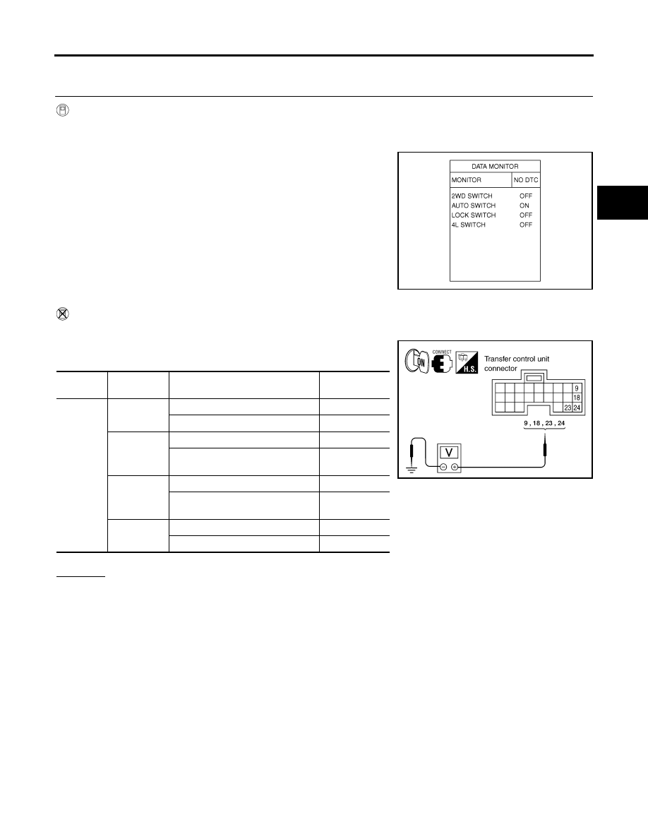
 With CONSULT-II

1.

Turn ignition switch “ON”. (Do not start engine.)

2.

Select “DATA MONITOR” mode for “ALL MODE AWD/4WD” with CONSULT-II.

3.

Read out ON/OFF switching action of the “2WD SWITCH”,
“AUTO SWITCH”, “LOCK SWITCH” and “4L SWITCH” while
operating 4WD shift switch.

 Without CONSULT-II

1.

Turn ignition switch “ON”. (Do not start engine.)

2.

Check voltage between transfer control unit harness connector
terminals and ground.

OK or NG

OK >> GO 

TO 

5.

NG

>> GO TO 2.

SDIA2697E

Connector

Terminal

Condition

Voltage 

(Approx.)

M152

9 - ground

4WD shift switch: 2WD

Battery voltage

4WD shift switch: AUTO, 4H or 4LO

0V

18 - ground

4WD shift switch: 4H

Battery voltage

4WD shift switch: 2WD, AUTO or 
4LO

 0V

23 - ground

4WD shift switch: 4LO

Battery voltage

4WD shift switch: 2WD, AUTO or 
4H

 0V

24 - ground

4WD shift switch: AUTO

Battery voltage

4WD shift switch: 2WD, 4H or 4LO

0V

WDIA0167E

TF-66

[ATX14B]

TROUBLE DIAGNOSIS FOR SYSTEM

2007 Pathfinder

2. 

CHECK 4WD SHIFT SWITCH POWER SUPPLY CIRCUIT

1.

Turn ignition switch “OFF”.  (Stay for at least 5 seconds.)

2.

Disconnect 4WD shift switch harness connector.

3.

Check voltage between 4WD shift switch harness connector ter-
minal 1 and ground.

4.

Turn ignition switch “ON”. (Do not start engine.)

5.

Check voltage between 4WD shift switch harness connector ter-
minal 1 and ground.

OK or NG 

OK

>> GO TO 3.

NG

>> Check the following. If any items are damaged, repair or 

replace damaged parts.

Harness for short or open between transfer shut off
relay harness connector E155 terminal 5.

Power suppy circuit for transfer control unit.  Refer to 

TF-56, "Power Supply Circuit For Transfer

Control Unit"

 .

3. 

CHECK HARNESS BETWEEN 4WD SHIFT SWITCH AND TRANSFER CONTROL UNIT

1.

Turn ignition switch “OFF”.  (Stay for at least 5 seconds.)

2.

Disconnect transfer control unit harness connector and the 4WD shift switch harness connector.

3.

Check continuity between the following terminals.

Transfer control unit harness connector M152 terminal 9 and
4WD shift switch harness connector M141 terminal 2.

Transfer control unit harness connector M152 terminal 18 and
4WD shift switch harness connector M141 terminal 5.

Transfer control unit harness connector M152 terminal 23 and
4WD shift switch harness connector M141 terminal 6.

Transfer control unit harness connector M152 terminal 24 and
4WD shift switch harness connector M141 terminal 3.

Also check harness for short to ground and short to power.

 OK or NG

 OK 

>> GO TO 4.

 NG

>> Repair or replace damaged parts.

Connector Terminal

Voltage 

(Approx.)

 M141

1 - Ground

0V

WDIA0183E

Connector

Terminal

Voltage (Approx.)

M141

1 - Ground

Battery voltage

WDIA0184E

Continuity should exist.

WDIA0185E

TROUBLE DIAGNOSIS FOR SYSTEM

TF-67

[ATX14B]

C

E

F

G

H

I

J

K

L

M

A

B

TF

2007 Pathfinder

4. 

CHECK 4WD SHIFT SWITCH

1.

Turn ignition switch “OFF”.  (Stay for at least 5 seconds.)

2.

Disconnect 4WD shift switch harness connector. 

3.

Operate 4WD shift switch and check continuity between 4WD
shift switch terminals.

OK or NG

OK

>> GO TO 5.

NG

>> Replace 4WD shift switch.

5. 

CHECK TRANSFER CONTROL UNIT

Check transfer control unit input/output signal. Refer to 

TF-37, "Transfer Control Unit Input/Output Signal Ref-

erence Values"

 .

OK or NG

OK

>> GO TO 6.

 NG

>> Check transfer control unit pin terminals for damage or loose connection with harness connector.

If any items are damaged, repair or replace damaged parts.

6. 

CHECK DTC

Perform the self-diagnosis, after driving a vehicle for a while.

OK or NG

OK

>> Inspection End.

NG

>> Replace transfer control unit. Refer to 

TF-132, "Removal and Installation"

 .

Connector

Terminal

Condition

Continuity

M141

1 - 2

4WD shift switch: 2WD

Yes

4WD shift switch: AUTO, 4H and 
4LO

No

1 - 3

4WD shift switch: AUTO

Yes

4WD shift switch: 2WD, 4H and 
4LO

No

1 - 4

4WD shift switch: 2WD

No

4WD shift switch: AUTO, 4H and 
4LO

Yes

1 - 5

4WD shift switch: 4H

Yes

4WD shift switch: 2WD, AUTO, 
and 4LO

No

1 - 6

4WD shift switch: 4LO

Yes

4WD shift switch: 2WD, AUTO 
and 4H

No

WDIA0168E

TF-68

[ATX14B]

TROUBLE DIAGNOSIS FOR SYSTEM

2007 Pathfinder

COMPONENT INSPECTION

1.

Turn ignition switch “OFF”.  (Stay for at least 5 seconds.)

2.

Disconnect 4WD shift switch harness connector. 

3.

Operate 4WD shift switch and check continuity between 4WD
shift switch terminals.

4.

If NG, replace the 4WD shift switch.

Wait Detection Switch

EDS0036K

CONSULT-II REFERENCE VALUE IN DATA MONITOR MODE

Data are reference value.

TRANSFER CONTROL UNIT TERMINALS AND REFERENCE VALUE

Data are reference value and are measured between each terminal and ground.

CAUTION:

When using a circuit tester to measure voltage for inspection, be sure not to extend forcibly any connector terminals.

Connector

Terminal

Condition

Continuity

M141

1 - 2

4WD shift switch: 2WD

Yes

4WD shift switch: AUTO, 4H and 
4LO

No

1 - 3

4WD shift switch: AUTO

Yes

4WD shift switch: 2WD, 4H and 
4LO

No

1 - 4

4WD shift switch: 2WD

No

4WD shift switch: AUTO, 4H and 
4LO

Yes

1 - 5

4WD shift switch: 4H

Yes

4WD shift switch: 2WD, AUTO, 
and 4LO

No

1 - 6

4WD shift switch: 4LO

Yes

4WD shift switch: 2WD, AUTO 
and 4H

No

WDIA0168E

Monitored item

Content

Condition

Display value

WAIT DETCT SW [ON/
OFF]

Condition of wait detection 
switch

Vehicle stopped

Engine running

A/T selector lever “N” 
position

Brake pedal depressed

4WD shift switch: 2WD, 
AUTO or 4H

OFF

4WD shift switch: 4H to 
4LO (While actuator 
motor is operating.)

OFF 

 ON

4WD shift switch: 4LO to 
4H (While actuator motor 
is operating.)

ON 

 OFF

4WD shift switch: 4LO

ON

Terminal

Wire 

color

Item

Condition

Data (Approx.)

43

O

Wait detection switch

Vehicle stopped

Engine running

A/T selector 
lever “N” position

Brake pedal 
depressed

4WD shift switch: 2WD, AUTO or 4H

Battery voltage

4WD shift switch: 4H to 4LO (While actua-
tor motor is operating.)

Battery volt-
age 

 0V

4WD shift switch: 4LO to 4H (While actua-
tor motor is operating.)

0V 

 Battery 

voltage

4WD shift switch: 4LO

0V

TROUBLE DIAGNOSIS FOR SYSTEM

TF-69

[ATX14B]

C

E

F

G

H

I

J

K

L

M

A

B

TF

2007 Pathfinder

DIAGNOSTIC PROCEDURE

1. 

CHECK WAIT DETECTION SWITCH SIGNAL

 With CONSULT-II

1.

Start engine.

2.

Select “DATA MONITOR” mode for “ALL MODE AWD/4WD” with CONSULT-II.

3.

Read out the value of “WAIT DETCT SW”.

 Without CONSULT-II

1.

Start engine.

2.

Check voltage between transfer control unit harness connector
terminal and ground.

OK or NG

OK >> GO 

TO 

5.

NG

>> GO TO 2.

2. 

CHECK HARNESS BETWEEN TRANSFER CONTROL UNIT AND WAIT DETECTION SWITCH

1.

Turn ignition switch “OFF”.  (Stay for at least 5 seconds.)

2.

Disconnect transfer control unit harness connector and the wait detection switch harness connector.

3.

Check continuity between transfer control unit harness connec-
tor M153 terminal 43 and wait detection switch harness connec-
tor F59 terminal 10.

Also check harness for short to ground and short to power.

OK or NG

OK

>> GO TO 3.

NG

>> Repair or replace damaged parts.

Condition

Display value

Vehicle stopped

Engine running

A/T selector lever “N” position

Brake pedal depressed

4WD shift switch: 2WD, AUTO 
or 4H

OFF

4WD shift switch: 4H to 4LO 
(While actuator motor is operat-
ing.)

OFF 

 ON

4WD shift switch: 4LO to 4H 
(While actuator motor is operat-
ing.)

ON 

 OFF

4WD shift switch: 4LO

ON

PDIA0221E

Connector

Terminal

Condition

Voltage 

(Approx.)

M153

43 - 

Ground

Vehicle stopped

Engine running

A/T selector lever 
“N” position

Brake pedal 
depressed

4WD shift switch: 
2WD, AUTO or 4H

Battery 
voltage

4WD shift switch: 4H 
to 4LO (While actua-
tor motor is operating.)

Battery 
voltage 

 0V

4WD shift switch: 4LO 
to 4H (While actuator 
motor is operating.)

0V 


Battery 
voltage

4WD shift switch: 4LO

0V

SDIA2701E

Continuity should exist.

SDIA2702E

TF-70

[ATX14B]

TROUBLE DIAGNOSIS FOR SYSTEM

2007 Pathfinder

3. 

CHECK GROUND CIRCUIT

1.

Turn ignition switch “OFF”.  (Stay for at least 5 seconds.)

2.

Disconnect wait detection switch harness connector.

3.

Check continuity between wait detection switch harness con-
nector F59 terminal 11 and ground.

Also check harness for short to power.

 OK or NG

 OK 

>> GO TO 4.

 NG

>> Repair open circuit or short to power in harness or con-

nectors.

4. 

CHECK WAIT DETECTION SWITCH

1.

Turn ignition switch “OFF”.  (Stay for at least 5 seconds.)

2.

Disconnect wait detection switch harness connector.

3.

Remove wait detection switch. Refer to 

TF-24, "Location of Electrical Parts"

 .

4.

Push and release wait detection switch and check continuity
between wait detection switch terminals 10 and 11.

OK or NG

OK

>> GO TO 5.

NG

>> Replace wait detection switch.  Refer to 

TF-24, "Loca-

tion of Electrical Parts"

 .

5. 

CHECK TRANSFER CONTROL UNIT

Check transfer control unit input/output signal. Refer to 

TF-37, "Transfer Control Unit Input/Output Signal Ref-

erence Values"

 .

OK or NG

OK

>> GO TO 6.

NG 

>> Check transfer control unit pin terminals for damage or loose connection with harness connector.

If any items are damaged, repair or replace damaged parts.

6. 

CHECK DTC

Perform the self-diagnosis, after driving a vehicle for a while.

OK or NG

OK

>> Inspection End.

NG

>> Replace transfer control unit. Refer to 

TF-132, "Removal and Installation"

 .

Continuity should exist.

SDIA2703E

Terminal

Condition

Continuity

10 - 11

Push wait detection switch

Yes

Release wait detection switch

No

WDIA0186E

TROUBLE DIAGNOSIS FOR SYSTEM

TF-71

[ATX14B]

C

E

F

G

H

I

J

K

L

M

A

B

TF

2007 Pathfinder

COMPONENT INSPECTION

1.

Turn ignition switch “OFF”.  (Stay for at least 5 seconds.)

2.

Disconnect wait detection switch harness connector.

3.

Remove wait detection switch. Refer to 

TF-24, "Location of Electrical Parts"

 .

4.

Push and release wait detection switch and check continuity
between wait detection switch terminals 10 and 11.

5.

If NG, replace the wait detection switch.  Refer to 

TF-24, "Loca-

tion of Electrical Parts"

 .

PNP Switch Signal (TCM)

EDS0036L

DIAGNOSTIC PROCEDURE

1. 

CHECK DTC WITH TCM

Perform self-diagnosis with TCM. Refer to 

TF-52, "SELF-DIAGNOSTIC PROCEDURE (WITH CONSULT-II)"

 .

Is any malfunction detected by self-diagnosis?

YES

>> Check the malfunctioning system.

NO

>> GO TO 2.

2. 

CHECK TRANSFER CONTROL UNIT

Check transfer control unit input/output signal. Refer to 

TF-37, "Transfer Control Unit Input/Output Signal Ref-

erence Values"

 .

OK or NG

OK

>> GO TO 3.

NG

>> Check transfer control unit pin terminals for damage or loose connection with harness connector.

If any items are damaged, repair or replace damaged parts.

3. 

CHECK DTC

Perform the self-diagnosis, after driving a vehicle for a while.

OK or NG

OK

>> Inspection End.

NG

>> Perform self-diagnosis with TCM again. Refer to 

TF-52, "SELF-DIAGNOSTIC PROCEDURE

(WITH CONSULT-II)"

 .

Terminal

Condition

Continuity

10 - 11

Push wait detection switch

Yes

Release wait detection switch

No

WDIA0186E

TF-72

[ATX14B]

TROUBLE DIAGNOSIS FOR SYSTEM

2007 Pathfinder

Actuator Motor

EDS0036M

CONSULT-II REFERENCE VALUE IN DATA MONITOR MODE

Data are reference value.

TRANSFER CONTROL UNIT TERMINALS AND REFERENCE VALUE

Data are reference value and are measured between each terminal and ground.

CAUTION:

When using a circuit tester to measure voltage for inspection, be sure not to extend forcibly any connector terminals.

Monitored item

Content

Condition

Display value

SHIFT ACT1 [ON/OFF]

Output condition to 
actuator motor (High)

Vehicle stopped

Engine running

A/T selector lever “N” 
position

Brake pedal depressed

4WD shift switch: 4H to 
4LO (“Wait” function is 
operating.)

ON

Except the above

OFF

SHIFT AC MON1 [ON/OFF]

Check signal for trans-
fer control unit signal 
output

Vehicle stopped

Engine running

A/T selector lever “N” 
position

Brake pedal depressed

4WD shift switch: 4H to 
4LO (“Wait” function is 
operating.)

ON

Except the above

OFF

SHIFT ACT2 [ON/OFF]

Output condition to 
actuator motor (Low)

Vehicle stopped

Engine running

A/T selector lever “N” 
position

Brake pedal depressed

4WD shift switch: 4LO to 
4H (“Wait” function is 
operating.)

ON

Except the above

OFF

SHIFT AC MON2 [ON/OFF]

Check signal for trans-
fer control unit signal 
output

Vehicle stopped

Engine running

A/T selector lever “N” 
position

Brake pedal depressed

4WD shift switch: 4LO to 
4H (“Wait” function is 
operating.)

ON

Except the above

OFF

Terminal

Wire 

color

Item

Condition

Data (Approx.)

4

SB

Transfer shift high relay

Vehicle stopped

Engine running

A/T selector 
lever “N” position

Brake pedal 
depressed

4WD shift switch: 4H to 4LO (“Wait” func-
tion is operating.)

Battery voltage

Except the above

0V

13

G

Transfer shift low relay

Vehicle stopped

Engine running

A/T selector 
lever “N” position

Brake pedal 
depressed

4WD shift switch: 4LO to 4H (“Wait” func-
tion is operating.)

Battery voltage

Except the above

0V

33

GR

Transfer shift high relay moni-
tor

Vehicle stopped

Engine running

A/T selector 
lever “N” position

Brake pedal 
depressed

4WD shift switch: 4H to 4LO (“Wait” func-
tion is operating.)

Battery voltage

Except the above

0V

42

Y

Transfer shift low relay moni-
tor

Vehicle stopped

Engine running

A/T selector 
lever “N” position

Brake pedal 
depressed

4WD shift switch: 4LO to 4H (“Wait” func-
tion is operating.)

Battery voltage

Except the above

0V


Content      ..     396      397      398      399     ..