Nissan Pathfinder (2007 year). Manual - part 392
ALL-MODE 4WD SYSTEM
TF-17
[ATX14B]
C
E
F
G
H
I
J
K
L
M
A
B
TF
2007 Pathfinder
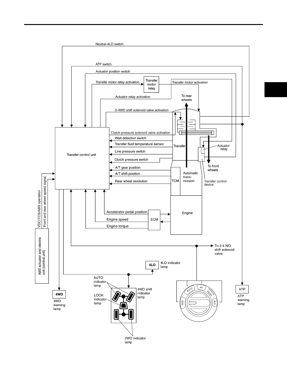
System Description
EDS00362
CONTROL SYSTEM
SDIA3396E
|
|
|
ALL-MODE 4WD SYSTEM TF-17 [ATX14B] C E F G H I J K L M A B TF 2007 Pathfinder System Description EDS00362 CONTROL SYSTEM SDIA3396E |