Nissan Pathfinder (2007 year). Manual - part 375
AUTOMATIC DRIVE POSITIONER
SE-39
C
D
E
F
G
H
J
K
L
M
A
B
SE
2007 Pathfinder
2.
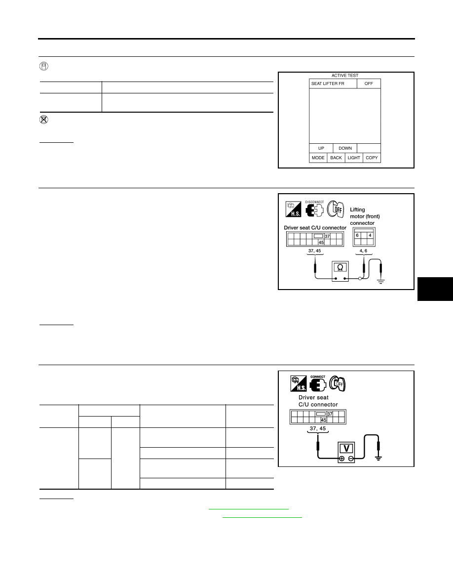
CHECK FUNCTION
With CONSULT-II
Check operation with “SEAT LIFTER FR” in ACTIVE TEST.
Without CONSULT-II
GO TO 3.
OK or NG
OK
>> Lifting motor (front) circuit is OK.
NG
>> GO TO 3.
3.
CHECK LIFTING MOTOR (FRONT) CIRCUIT HARNESS CONTINUITY
1.
Turn ignition switch OFF.
2.
Disconnect driver seat control unit and lifting motor (front).
3.
Check continuity between driver seat control unit connector P3
terminals 37, 45 and lifting motor (front) connector P6 terminals
4, 6.
4.
Check continuity between driver seat control unit connector P3
terminals 37, 45 and ground.
OK or NG
OK
>> GO TO 4.
NG
>> Repair or replace harness.
4.
CHECK DRIVER SEAT CONTROL UNIT OUTPUT SIGNAL
1.
Connect the driver seat control unit and lifting motor (front).
2.
Check voltage between driver seat control unit connector and
ground.
OK or NG
OK
>> Replace lifting motor (front). Refer to
.
NG
>> Replace driver seat control unit. Refer to
.
Test item
Description
SEAT LIFTER FR
The lifting motor (front) is activated by receiving the drive
signal.
PIIA0271E
37 - 6
: Continuity should exist.
45 - 4
: Continuity should exist.
37 - Ground
: Continuity should not exist.
45 - Ground
: Continuity should not exist.
LIIA0698E
Connector
Terminals
Condition
Voltage (V)
(Approx)
(+)
(-)
P3
37
Ground
Lifting switch (front) ON
(DOWN operation)
Battery voltage
Other than above
0
45
Llifting switch (front) ON
(UP operation)
Battery voltage
Other than above
0
PIIA4805E