Nissan Pathfinder (2007 year). Manual - part 356


  Index      Manuals     Nissan Pathfinder (2007 year) - Service and Repair Manual


Search            copyright infringement  


Content      ..     354      355      356      357     ..


Nissan Pathfinder (2007 year). Manual - part 356


SUNROOF

RF-25

C

D

E

F

G

H

J

K

L

M

A

B

RF

2007 Pathfinder

2.

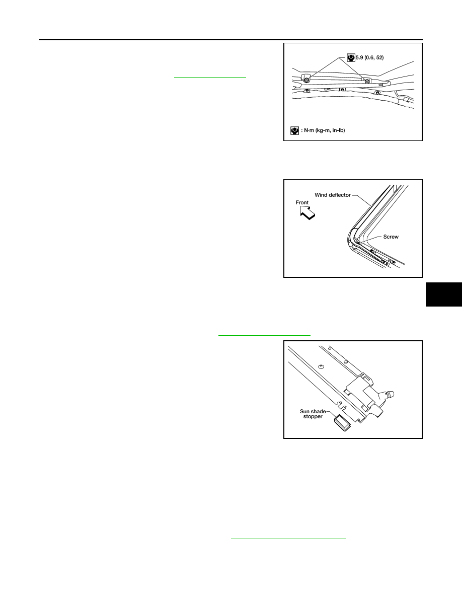
Install the glass lid assembly screws. (First tighten left front bolt,
then tighten right rear bolt on glass lid to prevent lid from moving
while tightening other bolts.) 

3.

Adjust the sunroof glass. Refer to 

RF-22, "Adjustment"

 .

WIND DEFLECTOR
Removal

1.

Open the sunroof.

2.

Remove screws from the left, center, and right side wind deflec-
tor holders.

3.

Remove the wind deflector from the sunroof frame assembly.

Installation

Installation is in the reverse order of removal.

SUNSHADE
Removal

1.

Remove the sunroof frame assembly. Refer to 

RF-24, "SUNROOF UNIT"

 .

2.

Remove the sunshade stoppers (2 points) from the rear end of
the sunroof frame assembly.

3.

Remove the sunshade assembly from the rear end of the sun-
roof frame assembly.

Installation

Installation is in the reverse order of removal.

SUNROOF MOTOR
Removal

CAUTION:

When removing the sunroof motor, be sure that the sunroof is in the fully closed position.

Never run the removed motor as a single unit.

1.

Position the sunroof assembly in the fully closed position.

2.

Remove the front roof console assembly. Refer to 

EI-31, "Removal and Installation"

 .

WIIA0252E

WIIA0424E

LIIA1672E

RF-26

SUNROOF

2007 Pathfinder

3.

Disconnect the harness connector from the sunroof motor
assembly.

4.

Remove the mounting screws and the sunroof motor assembly.

Installation

CAUTION:

Before installing the sunroof motor assembly, be sure to place the link and wire assembly in the sym-
metrical and fully closed position.

1.

Move the sunroof motor assembly laterally little by little so that
the gear is completely engaged into the wire on the sunroof unit
and the mounting surface becomes parallel. Then secure the
motor with bolts.

2.

Connect the harness connector to the sunroof motor assembly.

3.

Install the front roof console assembly. Refer to 

EI-31, "Removal and Installation"

 .

4.

Reset the sunroof motor memory. Refer to 

RF-12, "RE-TEACHING PROCEDURE"

 .

DRAIN HOSES
Removal

LIIA1673E

LIIA1674E

1.

Drain hoses

WIIA1072E

SUNROOF

RF-27

C

D

E

F

G

H

J

K

L

M

A

B

RF

2007 Pathfinder

1.

Remove the headlining. Refer to 

EI-31, "Removal and Installation"

 .

2.

Visually check the drain hoses for proper connections, damage or deterioration.

3.

Remove each drain hose and check visually for damage, cracks or deterioration.

4.

Pour water through the drain hose to check for damage.

If any damage is found, replace the drain hose.

Installation

Installation is in the reverse order of removal.

WEATHERSTRIP

Visually check weatherstrip for any damage, deterioration, or flattening. 

In the case of leakage around glass lid, close glass lid and pour water around it to find the damaged or
gaped portion, remove glass lid assembly. Refer to: 

RF-24, "Removal"

 .

If any damage is found, replace glass lid assembly. Refer to: 

RF-24, "GLASS LID"

 .

CAUTION:

Do not remove weatherstrip.

LINK AND WIRE ASSEMBLY

NOTE:
Before replacing any suspect part, be sure it is the source of the noise.

1.

Visually check to determine if a sufficient amount of petroleum jelly has been applied to the wire or rail
groove. If not, add petroleum jelly as required.

2.

Check wire for any damage or deterioration. If any damage is found, remove rear guide, then replace
wire.

LIIA0272E

RF-28

SUNROOF

2007 Pathfinder

RFD-1

REAR FINAL DRIVE

D  DRIVELINE/AXLE

CONTENTS

C

E

F

G

H

I

J

K

L

M

SECTION 

RFD

A

B

RFD

2007 Pathfinder

PRECAUTIONS .......................................................... 2

Precautions for Servicing Rear Final Drive  .............. 2

PREPARATION ........................................................... 3

Special Service Tools  ............................................... 3
Commercial Service Tools ........................................ 6

NOISE, VIBRATION AND HARSHNESS (NVH) 
TROUBLESHOOTING ................................................ 7

NVH Troubleshooting Chart  ..................................... 7

DESCRIPTION ............................................................ 8

Cross-Sectional View  ............................................... 8

DIFFERENTIAL GEAR OIL  ........................................ 9

Changing Differential Gear Oil  ................................. 9

DRAINING ............................................................. 9
FILLING ................................................................. 9

Checking Differential Gear Oil .................................. 9

OIL LEAKAGE AND OIL LEVEL  ........................... 9

FRONT OIL SEAL  .................................................... 10

Removal and Installation  ........................................ 10

REMOVAL ........................................................... 10
INSTALLATION ....................................................11

SIDE OIL SEAL  ........................................................ 12

Removal and Installation  ........................................ 12

REMOVAL ........................................................... 12
INSTALLATION ................................................... 12

CARRIER COVER  .................................................... 14

Removal and Installation  ........................................ 14

REMOVAL ........................................................... 14
INSTALLATION ................................................... 14

REAR FINAL DRIVE ASSEMBLY  ............................ 15

Removal and Installation  ........................................ 15

COMPONENTS ................................................... 15
REMOVAL ........................................................... 16
INSTALLATION ................................................... 17

Disassembly and Assembly .................................... 18

COMPONENTS ................................................... 18
ASSEMBLY INSPECTION AND ADJUSTMENT 

... 19

DISASSEMBLY ................................................... 21
INSPECTION AFTER DISASSEMBLY ................ 26
ADJUSTING AND SELECTING WASHERS  ....... 26
ASSEMBLY ......................................................... 32

SERVICE DATA AND SPECIFICATIONS (SDS)  ...... 38

General Specifications ............................................ 38
Inspection and Adjustment  ..................................... 38

DRIVE GEAR RUNOUT  ...................................... 38
SIDE GEAR CLEARANCE  .................................. 38
PRELOAD TORQUE  ........................................... 38
BACKLASH ......................................................... 38
COMPANION FLANGE RUNOUT ....................... 38
SELECTIVE PARTS  ............................................ 38

RFD-2

PRECAUTIONS

2007 Pathfinder

PRECAUTIONS

PFP:00001

Precautions for Servicing Rear Final Drive

EDS0039U

Before starting diagnosis of the vehicle, understand the symptoms well. Perform correct and systematic
operations. 

Check for the correct installation status prior to removal or disassembly. When matching marks are
required, be certain they do not interfere with the function of the parts they are applied to. 

Overhaul should be done in a clean work area, a dust proof area is recommended.

Before disassembly, completely remove sand and mud from the exterior of the unit, preventing them from
entering into the unit during disassembly or assembly.

Always use shop paper for cleaning the inside of components.

Avoid using cotton gloves or a shop cloth to prevent the entering of lint.

Check appearance of the disassembled parts for damage, deformation, and abnormal wear. Replace
them with new ones if necessary. 

Gaskets, seals and O-rings should be replaced any time the unit is disassembled.

Clean and flush the parts sufficiently and blow them dry.

Be careful not to damage sliding surfaces and mating surfaces.

When applying sealant, remove the old sealant from the mating surface; then remove any moisture, oil,
and foreign materials from the application and mating surfaces.

In principle, tighten nuts or bolts gradually in several steps working diagonally from inside to outside. If a
tightening sequence is specified, observe it.

During assembly, observe the specified tightening torque.

Add new differential gear oil, petroleum jelly, or multi-purpose grease, as specified.

PREPARATION

RFD-3

C

E

F

G

H

I

J

K

L

M

A

B

RFD

2007 Pathfinder

PREPARATION

PFP:00002

Special Service Tools

EDS0039V

The actual shapes of Kent-Moore tools may differ from those of special service tools illustrated here.

Tool number
(Kent-Moore No.)
Tool name

Description

KV40104000
(

)

Flange wrench

Removing and installing drive pinion lock nut
a: 85 mm (3.35 in) dia.
b: 65 mm (2.56 in) dia.

KV381054S0
(J-34286)
Puller

Removing front oil seal 

ST30720000
(J-25405)
Drift

Installing front oil seal

Installing drive pinion rear bearing outer 
race

a: 77 mm (3.03 in) dia.
b: 55.5 mm (2.185 in) dia.

ST36230000
(J-25840-A)
Sliding hammer 

Removing side flange

KV40104100
(

)

Attachment

Removing side flange

KV38100200
(J-26233)
Drift

Installing side oil seal
a: 65 mm (2.56 in) dia.
b: 49 mm (1.93 in) dia.

KV38107900
(J-39352)
Protector

Installing side flange

NT659

ZZA0601D

ZZA0811D

ZZA0803D

ZZA0804D

ZZA1143D

S-NT129

RFD-4

PREPARATION

2007 Pathfinder

KV38100800
(J-25604-01)
Attachment

Securing unit assembly
a: 541 mm (21.30 in)
b: 200 mm (7.87 in)

ST3127S000
(J-25765-A)
Preload gauge
1: GG91030000

(J-25765)
Torque wrench

2: HT62940000

(

)

Socket adapter (1/2

)

3: HT62900000

(

)

Socket adapter (3/8

)

Measuring drive pinion bearing preload torque 
and total preload torque

KV10111100
(J-37228)
Seal cutter

Removing carrier cover

ST3306S001
(

)

Differential side bearing puller set
1: ST33051001

(J-22888-20)
Puller

2: ST33061000

(J-8107-2)
Base

Removing and installing side bearing inner 
race
a: 28.5 mm (1.122 in) dia.
b: 38 mm (1.50 in) dia.

ST30031000
(J-22912-01)
Puller

Removing drive pinion rear bearing inner race

KV40105230
(

)

Drift

Installing drive pinion rear bearing outer race
a: 92 mm (3.62 in) dia.
b: 86 mm (3.39 in) dia.
c: 45 mm (1.77 in) dia.

ST30611000
(J-25742-1)
Drift bar

Installing drive pinion front bearing outer race 
(Use with ST30613000)

Tool number
(Kent-Moore No.)
Tool name

Description

SDIA0267E

NT124

S-NT046

NT072

ZZA0700D

PDIA0591E

S-NT090


Content      ..     354      355      356      357     ..