Index Manuals Nissan Pathfinder (2007 year) - Service and Repair Manual
Search copyright infringement
Content .. 294 295 296 297 ..
Nissan Pathfinder (2007 year). Manual - part 296
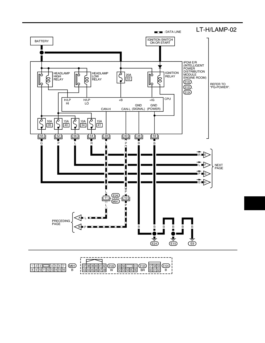
HEADLAMP (FOR USA)
LT-9
C
D
E
F
G
H
I
J
L
M
A
B
LT
2007 Pathfinder
WKWA2018E