Nissan Pathfinder (2007 year). Manual - part 258


  Index      Manuals     Nissan Pathfinder (2007 year) - Service and Repair Manual


Search            copyright infringement  


Content      ..     256      257      258      259     ..


Nissan Pathfinder (2007 year). Manual - part 258


PREPARATION

FSU-3

C

D

F

G

H

I

J

K

L

M

A

B

FSU

2007 Pathfinder

PREPARATION

PFP:00002

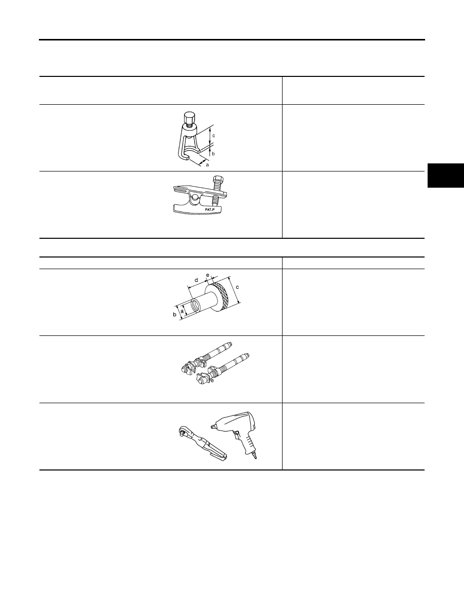
Special Service Tools

EES0022P

The actual shapes of Kent-Moore tools may differ from those of special service tools illustrated here.

Commercial Service Tools

EES0022Q

Tool number
(Kent-Moore No.)
Tool name

Description

ST29020001
(J-24319-01)
Gear arm puller

Removing ball joint for knuckle
a: 34 mm (1.34 in)
b: 6.5 mm (0.256 in)
c: 61.5 mm (2.421 in)

HT72520000
(J-25730-A)
Ball joint remover

Removing tie-rod outer end

NT694

NT146

Tool name

Description

Attachment wheel alignment

Measuring wheel alignment
a: Screw M24 x 1.5 pitch
b: 35 mm (1.38 in) dia.
c: 65 mm (2.56 in) dia.
d: 56 mm (2.20 in)
e: 12 mm (0.47 in)

Spring compressor

Removing and installing coil spring

Power tool

Loosening bolts and nuts

NT148

NT717

PBIC0190E

FSU-4

NOISE, VIBRATION, AND HARSHNESS (NVH) TROUBLESHOOTING

2007 Pathfinder

NOISE, VIBRATION, AND HARSHNESS (NVH) TROUBLESHOOTING

PFP:00003

NVH Troubleshooting Chart

EES0022R

Use the chart below to help you find the cause of the symptom. Repair or replace parts as necessary.

x: Applicable

Reference page

FS

U-

5

FS

U-

10

FS

U-

5

FS

U-

5

FS

U-

21

FS

U-

6

FS

U-

6

FS

U-

6

FA

X

-4

, "

N

V

H

 T

rou

bl

e

s

ho

ot

ing C

h

a

rt

"

FF

D-

6,

 "

N

V

H

 T

rou

bl

e

s

ho

ot

ing 

C

h

a

rt

"

FA

X

-4

, "

N

V

H

 T

rou

bl

e

s

ho

ot

ing C

h

a

rt

"

WT

-4

, "

N

V

H

 T

rou

bl

e

s

ho

ot

in

g C

h

a

rt

"

WT

-4

, "

N

V

H

 T

rou

bl

e

s

ho

ot

in

g C

h

a

rt

"

BR

-5

, "

N

V

H

 T

rou

bl

e

s

ho

ot

in

g C

h

a

rt

"

PS

-5

, "

N

V

H

 T

rou

bl

e

s

ho

ot

in

g C

h

a

rt

"

Possible Cause and
SUSPECTED PARTS

Im

p

rop

er

 i

n

st

al

la

ti

o

n

loos

en

ess

S

h

o

ck a

b

s

o

rb

er

 d

e

fo

rm

at

io

n,

d

a

m

age

 or

 de

fl

ec

ti

on

B

u

s

h

in

g

 or

 m

o

un

ti

ng

 de

te

ri

or

a

ti

o

n

P

a

rt

s in

te

rfe

re

n

ce

S

p

ri

n

g

 fa

tig

u

e

Su

sp

e

n

s

ion

 l

o

o

s

en

es

s

In

c

o

rr

e

c

t w

h

ee

l al

ig

nm

en

t

S

ta

b

iliz

e

r b

a

fa

ti

g

u

e

D

R

IV

E

 SH

AF

T

D

IFF

ER

EN

TI

AL

W

H

E

E

L

 HU

B A

N

D

 BE

AR

IN

G

TI

R

E

S

RO

AD

 W

H

E

E

L

BR

AK

ES

ST

EE

RI

N

G

Symptom

Noise

×

×

×

×

×

×

×

×

×

×

×

×

×

Shake

×

×

×

×

×

×

×

×

×

×

×

Vibration

×

×

×

×

×

×

×

×

×

Shimmy

×

×

×

×

×

×

×

×

×

×

Shudder

×

×

×

×

×

×

×

×

Poor quality ride or handling

×

×

×

×

×

×

×

×

×

×

FRONT SUSPENSION ASSEMBLY

FSU-5

C

D

F

G

H

I

J

K

L

M

A

B

FSU

2007 Pathfinder

FRONT SUSPENSION ASSEMBLY

PFP:54010

Components

EES0022S

1.

Dust cover

2.

Shock absorber

3.

Upper link

4.

Steering knuckle

5.

Cotter pin

6.

Washer

7.

Jounce bumper

8.

Bolt

9.

Lower link

10. Connecting rod

11. Stabilizer bar bushing

12. Stabilizer bar bracket

13. Stabilizer bar

14. Coil spring

15. Dust cover cap

16. Upper spring seat

17. Spacer

18. Shock absorber mounting insulator

19. Spacer

20. Washer

21. Cap

Front

WEIA0151E

FSU-6

ON-VEHICLE SERVICE

2007 Pathfinder

ON-VEHICLE SERVICE

PFP:00000

Front Suspension Parts

EES0022T

Check front suspension parts for excessive play, cracks, wear and
other damage.

Shake each front wheel to check for excessive play. If looseness
is noted:

inspect wheel bearing end play. Refer to 

FAX-5, "WHEEL

BEARING INSPECTION"

 .

check ball joint end play. Refer to 

FSU-15, "Inspection"

 .

Make sure that the cotter pin is inserted in drive shaft end (4WD
only).

Retighten all nuts and bolts to the specified torque.

Check shock absorber for oil leakage and other damage.

Check suspension ball joint for grease leakage and ball joint
dust cover for cracks and other damage.

Front Wheel Alignment

EES0022U

PRELIMINARY INSPECTION

WARNING:

Always adjust the alignment with the vehicle on a flat surface.

NOTE:
If alignment is out of specification, inspect and replace any damaged or worn rear suspension parts before
making any adjustments.

1.

Check and adjust the wheel alignment with the vehicle under unladen conditions. “Unladen conditions”
means that the fuel, coolant, and lubricant are full; and that the spare tire, jack, hand tools and mats are in
their designated positions.

2.

Check the tires for incorrect air pressure and excessive wear.

3.

Check the wheels for run out and damage. Refer to 

WT-5, "Inspection"

 .

4.

Check the wheel bearing axial end play. Refer to 

FAX-5, "WHEEL BEARING INSPECTION"

 .

5.

Check the shock absorbers for leaks or damage.

6.

Check each mounting point of the suspension components for any excessive looseness or damage.

7.

Check each link, arm, and the suspension member for any damage.

8.

Check the vehicle height. Refer to 

FSU-21, "Wheelarch Height (Unladen*

1

 )"

 .

GENERAL INFORMATION AND RECOMMENDATIONS

1.

A Four-Wheel Thrust Alignment should be performed.

This type of alignment is recommended for any NISSAN vehicle.

The four-wheel “thrust” process helps ensure that the vehicle is properly aligned and the steering wheel
is centered.

The alignment machine itself should be capable of accepting any NISSAN vehicle.

The alignment machine should be checked to ensure that it is level.

2.

Make sure the alignment machine is properly calibrated.

Suspension component torques

: Refer to 

FSU-5, 

"Components"

 . 

SMA525A

SFA392B

ON-VEHICLE SERVICE

FSU-7

C

D

F

G

H

I

J

K

L

M

A

B

FSU

2007 Pathfinder

Your alignment machine should be regularly calibrated in order to give correct information.

Check with the manufacturer of your specific alignment machine for their recommended Service/Cali-
bration Schedule.

THE ALIGNMENT PROCESS

IMPORTANT: Use only the alignment specifications listed in this Service Manual. Refer to 

FSU-20, "Wheel

Alignment (Unladen*1)*6"

 .

1.

When displaying the alignment settings, many alignment machines use “indicators”: (Green/red, plus or
minus, Go/No Go). Do NOT use these indicators.

The alignment specifications programmed into your alignment machine that operate these indicators
may not be correct.

This may result in an ERROR.

2.

Some newer alignment machines are equipped with an optional “Rolling Compensation” method to “com-
pensate” the sensors (alignment targets or head units). Do NOT use this “Rolling Compensation”
method.

Use the “Jacking Compensation” method. After installing the alignment targets or head units, raise the
vehicle and rotate the wheels 1/2 turn both ways.

See Instructions in the alignment machine you are using for more information.

CAMBER AND CASTER

1.

Measure camber and caster of both the right and left wheels
with a suitable alignment gauge and adjust as necessary to
specification.

NOTE:
Some vehicles may be equipped with straight (non-adjustable)
lower link bolts and washers. In order to adjust camber and
caster on these vehicles, first replace the lower link bolts and
washers with adjustable (cam) bolts and washers.

2.

If outside of the specified value, adjust camber and caster using
the adjusting bolts in the front lower link.

CAUTION:

After adjusting the camber then check the toe-in.

NOTE:
Camber changes about 3' (0.05

°

) minutes with each graduation

of one adjusting bolt. Refer to table below for examples of lower
link adjusting bolt effect on camber and caster. 

3.

Tighten the adjusting bolt nuts to specification. Refer to 

FSU-5, "Components"

 .

Camber

: Refer to 

FSU-6, "Front Wheel Alignment"

 .

SRA096A

WEIA0115E

Rear adjusting 
bolt

1 In

1 Out

1 In

1 Out

0

0

1 In

1 Out

Front adjusting 
bolt

1 Out

1 In

1 In

1 Out

1 In

1 Out

0

0

Camber
Degree minute 
(Decimal degree)

0 (0)

0 (0)

7' (0.12

°

)

- 7' (-0.12

°

)

3'  (0.05

°

)

- 3' (-0.05

°

)

3'  (0.05

°

)

- 3' (-0.05

°

)

Caster
Degree minute 
(Decimal degree)

- 12' (-0.20

°

)

12' (0.20

°

)

0 (0)

0 (0)

6' (0.10

°

)

- 6' (-0.10

°

)

- 6' (-0.10

°

)

6'  (0.10

°

)

FSU-8

ON-VEHICLE SERVICE

2007 Pathfinder

TOE-IN

WARNING:

Always perform the following procedure on a flat surface.

Make sure that no person is in front of the vehicle before pushing it.

1.

Bounce the front of vehicle up and down to stabilize the vehicle height (posture).

2.

Push the vehicle straight ahead about 5 m (16 ft).

3.

Put a mark on base line of the tread (rear side) of both front tires
at the same height as hub center as shown. These marks are
measuring points.

4.

Measure the distance “A” on the rear side of the front tires as
shown.

5.

Push the vehicle slowly ahead to rotate the wheels 180

°

degrees (1/2 a turn).

CAUTION:

If the wheels have rotated more than 180

°

 degrees (1/2

turn), start this procedure again from the beginning. Never
push the vehicle backward.

6.

Measure the distance “B” on the front side of the front tires at the
same marks as shown. Total toe-in is calculated as “A” – “B”.

7.

Adjust the toe-in by varying the length of the steering outer tie-
rods.

a.

Loosen the outer tie-rod lock nuts.

b.

Adjust the toe-in by screwing the outer tie-rods in or out.

c.

Tighten the outer tie-rod lock nuts to specification.

AFA050

Total toe-in

: Refer to 

FSU-20, "Wheel Alignment 

(Unladen*1)*6"

 .

SFA234AC

Standard length “L”

: Refer to 

PS-15, "POWER 

STEERING GEAR AND LINK-
AGE"

 .

Lock nut 

: Refer to 

PS-15, "Removal and 

Installation"

 .

SFA486A

ON-VEHICLE SERVICE

FSU-9

C

D

F

G

H

I

J

K

L

M

A

B

FSU

2007 Pathfinder

FRONT WHEEL TURNING ANGLE

NOTE:
Check front wheel turning angle after the toe-in inspection.

1.

Place front wheels on turning radius gauges in straight ahead
position and rear wheels on stands so that vehicle can be level.
Check the maximum inner and outer wheel turning angles for LH
and RH road wheels.

2.

Start engine and run at idle, turn steering wheel all the way right
and left, measure the turning angle.

Any turning angles are not adjustable. If any of steering
angles are out of the specification, check if the following parts
are worn or damaged.

Steering gear

Steering column

Front suspension components
If found that they are worn or damaged, replace them with new ones.

Wheel turning angle 
(full turn)

: Refer to 

FSU-20, "Wheel 

Alignment (Unladen*1)*6"

 .

SFA439BA

FSU-10

COIL SPRING AND SHOCK ABSORBER

2007 Pathfinder

COIL SPRING AND SHOCK ABSORBER

PFP:56210

Removal and Installation

EES0022V

REMOVAL

1.

Remove the wheel and tire using power tool.

2.

Support the lower link using a suitable jack.

3.

Remove connecting rod upper joints from stabilizer bar using power tool. Refer to 

FSU-5, "Components"

 .

Swing stabilizer bar down, repositioning it out of the way to access shock absorber lower mount.

4.

Remove the shock absorber lower bolt and nut using power tool.

5.

Remove the three shock absorber upper mounting nuts using
power tool.

6.

Remove the coil spring and shock absorber assembly.

Turn steering knuckle out to gain enough clearance for
removal.

INSTALLATION

Installation is in the reverse order of removal.

The step in the strut assembly lower seat faces outside of vehicle.

Tighten all nuts and bolts to specification. Refer to 

FSU-5, "Components"

 .

When installing wheel and tire, refer to 

WT-7, "Rotation"

 .

Disassembly and Assembly

EES0022W

DISASSEMBLY

1.

Set the shock absorber in a vise, then loosen (without removing)
the piston rod lock nut as shown.

CAUTION:

Do not remove piston rod lock nut at this time.

2.

Compress the coil spring using commercial service tool until the
shock absorber mounting insulator can be turned by hand.

WARNING:

Make sure that the pawls of the two spring compressors are
firmly hooked on the coil spring. The spring compressors
must be tightened alternately and evenly so as not to tilt the
coil spring.

3.

Remove the piston rod lock nut.

Discard the piston rod lock nut, use a new nut for assembly.

4.

Remove the components from the shock absorber.

Keep the coil spring compressed in the commercial service
tool if reusing it for assembly.

INSPECTION AFTER DISASSEMBLY
Shock Absorber Assembly

Check for smooth operation through a full stroke, both compression and extension.

Check for oil leakage on welded or gland packing portions.

Check piston rod for cracks, deformation or other damage and replace if necessary.

WEIA0116E

SSU002

SSU003


Content      ..     256      257      258      259     ..