Nissan Pathfinder (2007 year). Manual - part 257


  Index      Manuals     Nissan Pathfinder (2007 year) - Service and Repair Manual


Search            copyright infringement  


Content      ..     255      256      257      258     ..


Nissan Pathfinder (2007 year). Manual - part 257


FUEL TANK

FL-13

C

D

E

F

G

H

I

J

K

L

M

A

FL

2007 Pathfinder

REMOVAL

WARNING:

Follow the “General Precautions” before working on the fuel system. Refer to 

FL-2, "General Precau-

tions"

 .

1.

Remove the fuel filler cap to release the pressure from inside the fuel tank.

2.

Remove the LH rear wheel and tire. Refer to 

WT-7, "Rotation"

 .

3.

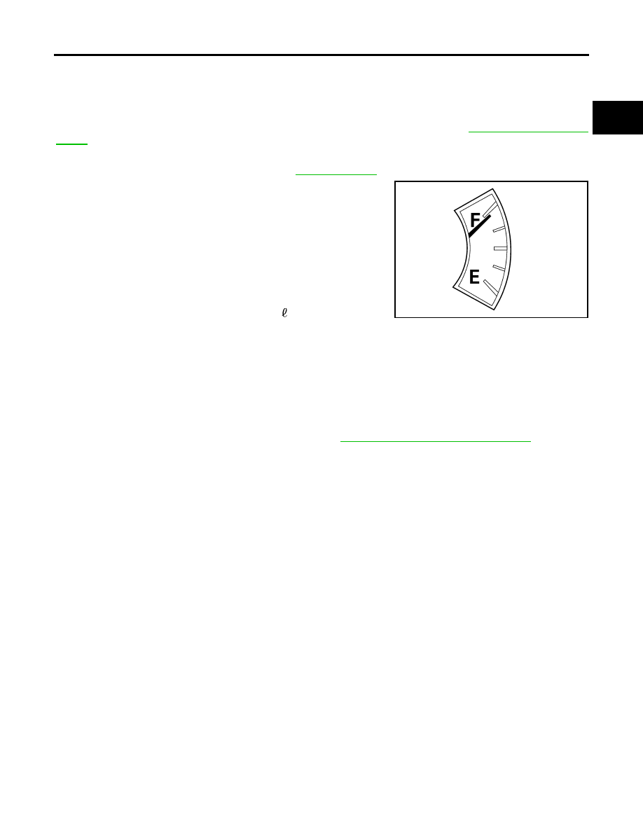
Check the fuel level on level gauge. If the fuel gauge indicates
more than the level as shown (full or almost full), drain the fuel
from the fuel tank until the fuel gauge indicates the level as
shown, or less.

NOTE:
Fuel will be spilled when removing the fuel level sensor, fuel fil-
ter, and fuel pump assembly for the fuel level is above the fuel
level sensor, fuel filter, and fuel pump assembly fuel tank open-
ing.

As a guide, the fuel level reaches the fuel gauge position as
shown, or less, when approximately 15   (4 US gal, 3 1/4 Imp
gal) of fuel are drained from the fuel tank. 

If the fuel pump does not operate, use the following procedure to drain the fuel to the specified level.

a.

Insert a suitable hose of less than 15 mm (0.59 in) diameter into the fuel filler pipe through the fuel filler
opening to drain the fuel from fuel filler pipe.

b.

Remove the fuel filler pipe shield.

c.

Disconnect the fuel filler hose from the fuel filler pipe.

d.

Insert a suitable hose into the fuel tank through the fuel filler hose to drain the fuel from the fuel tank.

4.

Release the fuel pressure from the fuel lines. Refer to 

EC-79, "FUEL PRESSURE RELEASE"

 .

5.

Disconnect the battery negative terminal.

6.

Disconnect the lower fuel filler hose from the fuel tank, the EVAP hose, and the vent pipe quick connector.

Disconnect the fuel feed hose from the molded clip in the side of the fuel tank.

Disconnect the quick connector as follows:

Hold the sides of the connector, push in the tabs and pull out the tube.

If the connector and the tube are stuck together, push and pull several times until they start to move.
Then disconnect them by pulling.

13. Fuel filler hose grommet

14.

Fuel filler cap

15. EVAP canister hose

16. Clamp

Front

WBIA0390E

FL-14

FUEL TANK

2007 Pathfinder

CAUTION:

The quick connector can be disconnected when the tabs
are completely depressed. Do not twist the quick connec-
tor more than necessary.

Do not use any tools to disconnect the quick connector.

Keep the resin tube away from heat. Be especially careful
when welding near the tube.

Prevent any acid liquids such as battery electrolyte, from
getting on the resin tube.

Do not bend or twist the resin tube during connection. 

Do not remove the remaining retainer on the hard tube (or
the equivalent) except when the resin tube or the retainer
is replaced.

When the resin tube or hard tube, or the equivalent, is 
replaced, also replace the retainer with a new one (semi-
transparent colored retainer).

To keep the quick connector clean and to avoid damage
and contamination from foreign materials, cover the
quick connector with plastic bags or suitable material as
shown.      

7.

Remove the four bolts and remove the fuel tank shield.

8.

Remove the propeller shaft. Refer to 

PR-9, "REAR PROPELLER SHAFT"

 .

9.

Support the fuel tank using a suitable lift jack.

10. Remove the three fuel tank strap bolts while supporting the fuel

tank with a suitable lift jack.

11. Remove the fuel tank straps and slowly lower the fuel tank to access the top of the fuel level sensor, fuel

filter and fuel pump assembly.

CAUTION:

Do not lower the fuel tank too far to prevent damage to the fuel feed hose and the fuel level sensor,
fuel filter and fuel pump assembly connector.

PBIC1268E

PBIC0163E

LBIA0413E

FUEL TANK

FL-15

C

D

E

F

G

H

I

J

K

L

M

A

FL

2007 Pathfinder

12. Disconnect the fuel level sensor, fuel filter, and fuel pump

assembly electrical connector, and the fuel feed hose.

Disconnect the quick connector as follows:

Hold the sides of the connector, push in the tabs and pull out
the tube.

If the connector and the tube are stuck together, push and pull
several times until they start to move. Then disconnect them
by pulling.

CAUTION:

The quick connector can be disconnected when the tabs
are completely depressed. Do not twist the quick connec-
tor more than necessary.

Do not use any tools to disconnect the quick connector.

Keep the resin tube away from heat. Be especially careful
when welding near the tube.

Prevent any acid liquids such as battery electrolyte, from
getting on the resin tube.

Do not bend or twist the resin tube during connection. 

Do not remove the remaining retainer on the hard tube (or
the equivalent) except when the resin tube or the retainer
is replaced.

When the resin tube or hard tube, or the equivalent, is 
replaced, also replace the retainer with a new one (semi-
transparent colored retainer).

LBIA0412E

SFE562A

PBIC1268E

FL-16

FUEL TANK

2007 Pathfinder

To keep the quick connector clean and to avoid damage
and contamination from foreign materials, cover the
quick connector with plastic bags or suitable material as
shown.      

13. Lower the fuel tank using a suitable lift jack and remove the fuel tank.

14. Disconnect the EVAP hose from the fuel pump and remove the EVAP hose from the molded clip in the top

of the fuel tank.

15. Remove the lock ring using Tool.

16. Remove the fuel level sensor, fuel filter, and fuel pump assem-

bly.

CAUTION:

Do not bend the float arm during removal.

Avoid impacts such as dropping when handling the com-
ponents.

INSTALLATION

Installation is in the reverse order of removal.

Connect the quick connector as follows:

Check the connection for any damage or foreign materials.

Align the connector with the pipe, then insert the connector straight into the pipe until a click is heard.

After connecting the quick connector, make sure that the con-
nection is secure by checking as follows:

Pull the tube and the connector to make sure they are securely
connected.

Visually inspect the connector to make sure the two retainer tabs
are securely connected.

CAUTION:

Do not bend the float arm during installation.

Avoid impacts such as dropping when handling the compo-
nents.

INSPECTION AFTER INSTALLATION

1.

Turn the ignition switch ON but do not start engine, then check the fuel pipe and hose connections for
leaks while applying fuel pressure.

2.

Start the engine and rev it above idle, then check that there are no fuel leaks at any of the fuel pipe and
hose connections.

PBIC0163E

Tool number

(J-45722)

LBIA0445E

PBIC1653E

SERVICE DATA AND SPECIFICATIONS (SDS)

FL-17

C

D

E

F

G

H

I

J

K

L

M

A

FL

2007 Pathfinder

SERVICE DATA AND SPECIFICATIONS (SDS)

PFP:00030

Standard and Limit

EBS00QUG

Fuel tank capacity

80 

 (21 1/8 US gal, 17 5/8 Imp gal)

FL-18

SERVICE DATA AND SPECIFICATIONS (SDS)

2007 Pathfinder

FSU-1

FRONT SUSPENSION

E  SUSPENSION

CONTENTS

C

D

F

G

H

I

J

K

L

M

SECTION 

FSU

A

B

FSU

2007 Pathfinder

PRECAUTIONS .......................................................... 2

Precautions for Supplemental Restraint System 
(SRS) “AIR BAG” and “SEAT BELT PRE-TEN-
SIONER” .................................................................. 2
Precautions .............................................................. 2

PREPARATION ........................................................... 3

Special Service Tools  ............................................... 3
Commercial Service Tools ........................................ 3

NOISE, VIBRATION, AND HARSHNESS (NVH) 
TROUBLESHOOTING ................................................ 4

NVH Troubleshooting Chart  ..................................... 4

FRONT SUSPENSION ASSEMBLY ........................... 5

Components ............................................................. 5

ON-VEHICLE SERVICE  ............................................. 6

Front Suspension Parts ............................................ 6
Front Wheel Alignment ............................................. 6

PRELIMINARY INSPECTION  ............................... 6
GENERAL INFORMATION AND RECOMMEN-
DATIONS .............................................................. 6
THE ALIGNMENT PROCESS  .............................. 7
CAMBER AND CASTER ....................................... 7
TOE-IN .................................................................. 8
FRONT WHEEL TURNING ANGLE  ..................... 9

COIL SPRING AND SHOCK ABSORBER ............... 10

Removal and Installation  ........................................ 10

REMOVAL ........................................................... 10
INSTALLATION ................................................... 10

Disassembly and Assembly  ................................... 10

DISASSEMBLY ................................................... 10
INSPECTION AFTER DISASSEMBLY  ............... 10
ASSEMBLY ..........................................................11

STABILIZER BAR  ..................................................... 12

Removal and Installation  ........................................ 12

REMOVAL ........................................................... 12
INSPECTION AFTER REMOVAL  ....................... 12
INSTALLATION ................................................... 12

UPPER LINK ............................................................. 13

Removal and Installation  ........................................ 13

REMOVAL ........................................................... 13
INSPECTION AFTER REMOVAL  ....................... 13
INSTALLATION ................................................... 13

LOWER LINK ............................................................ 14

Removal and Installation  ........................................ 14

REMOVAL ........................................................... 14
INSPECTION AFTER REMOVAL  ....................... 14
INSTALLATION ................................................... 14

UPPER BALL JOINT AND LOWER BALL JOINT ... 15

Removal and Installation  ........................................ 15
Inspection ............................................................... 15

SWINGING FORCE  ............................................ 15
TURNING FORCE  .............................................. 15
VERTICAL END PLAY  ........................................ 16

KNUCKLE ................................................................. 17

On-Vehicle Inspection and Service ......................... 17
Removal and Installation  ........................................ 17

REMOVAL ........................................................... 17
INSPECTION AFTER REMOVAL  ....................... 18
INSTALLATION ................................................... 19

SERVICE DATA AND SPECIFICATIONS (SDS)  ...... 20

General Specifications (Front) ................................ 20
Spring Free Height  ................................................. 20
Wheel Alignment (Unladen*1)*6 ............................. 20
Ball Joint  ................................................................. 21

Wheelarch Height (Unladen*

1

 )  .............................. 21

FSU-2

PRECAUTIONS

2007 Pathfinder

PRECAUTIONS

PFP:00001

Precautions for Supplemental Restraint System (SRS) “AIR BAG” and “SEAT 
BELT PRE-TENSIONER”

EES002BN

The Supplemental Restraint System such as “AIR BAG” and “SEAT BELT PRE-TENSIONER”, used along
with a front seat belt, helps to reduce the risk or severity of injury to the driver and front passenger for certain
types of collision. This system includes seat belt switch inputs and dual stage front air bag modules. The SRS
system uses the seat belt switches to determine the front air bag deployment, and may only deploy one front
air bag, depending on the severity of a collision and whether the front occupants are belted or unbelted.
Information necessary to service the system safely is included in the SRS and SB section of this Service Man-
ual.

WARNING:

To avoid rendering the SRS inoperative, which could increase the risk of personal injury or death
in the event of a collision which would result in air bag inflation, all maintenance must be per-
formed by an authorized NISSAN/INFINITI dealer.

Improper maintenance, including incorrect removal and installation of the SRS, can lead to per-
sonal injury caused by unintentional activation of the system. For removal of Spiral Cable and Air
Bag Module, see the SRS section.

Do not use electrical test equipment on any circuit related to the SRS unless instructed to in this
Service Manual. SRS wiring harnesses can be identified by yellow and/or orange harnesses or
harness connectors.

Precautions

EES0022O

When installing the rubber bushings, the final tightening must be done under unladen condition and with
the tires on level ground. Oil will shorten the life of the rubber bushings, so wipe off any spilled oil immedi-
ately.

Unladen condition means the fuel tank, engine coolant and lubricants are at the full specification. The
spare tire, jack, hand tools, and mats are in their designated positions.

After installing suspension components, check the wheel alignment.

Lock nuts are not reusable. Always use new lock nuts for installation. New lock nuts are pre-oiled, do not
apply any additional lubrication.


Content      ..     255      256      257      258     ..