Nissan Pathfinder (2007 year). Manual - part 253
FRONT FINAL DRIVE ASSEMBLY
FFD-17
C
E
F
G
H
I
J
K
L
M
A
B
FFD
2007 Pathfinder
Tooth Contact
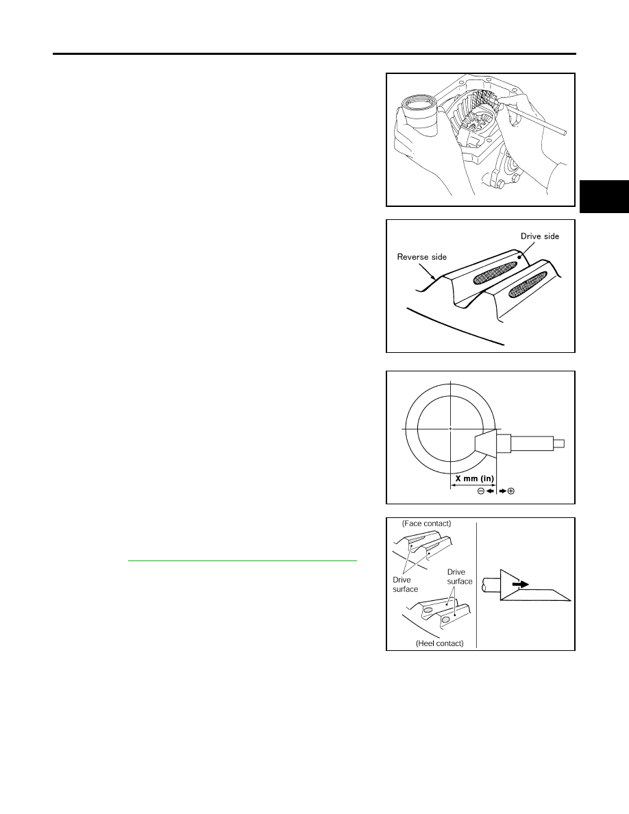
1.
Apply red lead to the drive gear.
NOTE:
Apply red lead to both faces of three to four gears, at four loca-
tions evenly spaced on the drive gear.
2.
Rotate the drive gear back and forth several times. Then check
for correct drive pinion to drive gear tooth contact as shown.
CAUTION:
Check tooth contact on drive side and reverse side.
●
If the tooth contact is improperly adjusted, adjust the drive pin-
ion height (dimension X).
–
If the tooth contact is near the face (face contact), or near the
heel (heel contact), use a thicker drive pinion height adjusting
washer to move drive pinion closer to the drive gear.
Refer to
FFD-35, "Drive Pinion Height Adjusting Washer"
SPD357
SDIA0570E
SDIA0517E
PDIA0440E