Nissan Pathfinder (2007 year). Manual - part 238
TIMING CHAIN
EM-61
C
D
E
F
G
H
I
J
K
L
M
A
EM
2007 Pathfinder
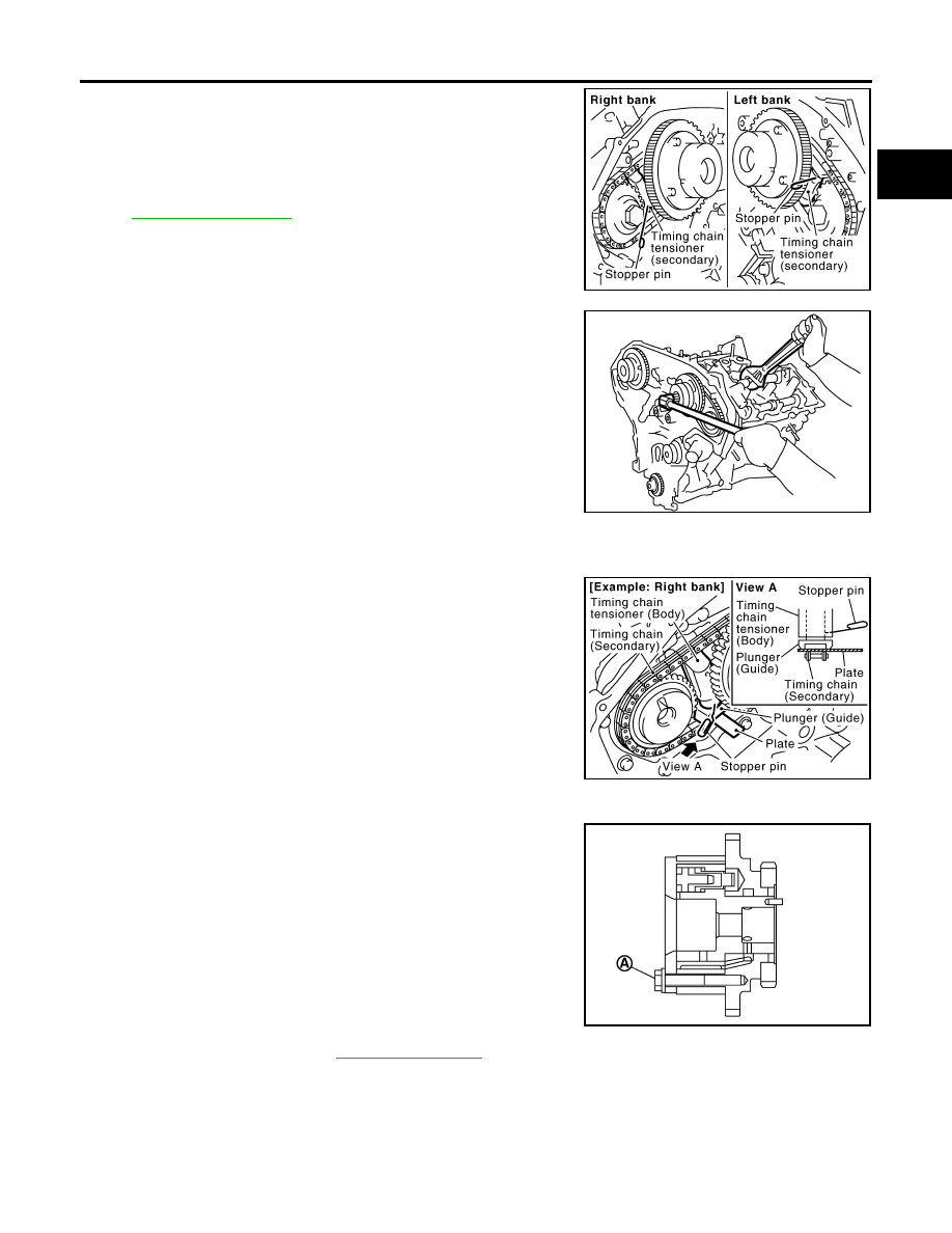
a.
Attach suitable stopper pin to the right and left timing chain ten-
sioners (secondary).
NOTE:
●
Use approximately 0.5 mm (0.02 in) dia. hard metal pin as a
stopper pin.
●
For removal of timing chain tensioner (secondary), refer to
. [Removing camshaft bracket (No. 1)
is required.]
b.
Remove camshaft sprocket (INT and EXH) bolts.
●
Secure the hexagonal portion of camshaft using wrench to
loosen bolts.
CAUTION:
Do not loosen bolts with securing anything other than the
camshaft hexagonal portion or with tensioning the timing
chain.
c.
Remove timing chain (secondary) together with camshaft sprockets.
●
Turn camshaft slightly to secure slackness of timing chain on timing chain tensioner (secondary) side.
●
Insert 0.5 mm (0.020 in)-thick metal or resin plate between
timing chain and timing chain tensioner plunger (guide).
Remove timing chain (secondary) together with camshaft
sprockets with timing chain loose from guide groove.
CAUTION:
Be careful of plunger coming off when removing timing
chain (secondary). This is because plunger of timing
chain tensioner (secondary) moves during operation,
leading to coming off of fixed stopper pin.
NOTE:
Camshaft sprocket (INT) is a one piece integrated design
sprockets for timing chain (primary) and for timing chain (sec-
ondary).
●
When handling camshaft sprocket (INT), be careful of the fol-
lowing:
CAUTION:
●
Handle carefully to avoid any shock to camshaft
sprocket.
●
Do not disassemble. (Do not loosen bolts “A” as
shown).
28. Remove water pump. Refer to
.
PBIC2047E
KBIA1698J
PBIC1978E
PBIC2920E