Nissan Pathfinder (2007 year). Manual - part 236
ROCKER COVER
EM-45
C
D
E
F
G
H
I
J
K
L
M
A
EM
2007 Pathfinder
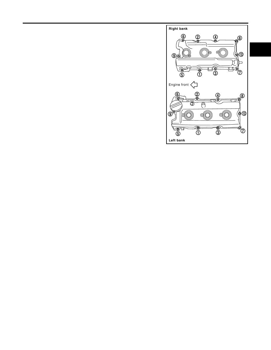
4.
Tighten bolts in two steps separately in numerical order as
shown.
5.
Install new O-ring and PCV valve to rocker cover (right bank), if removed.
6.
Install PCV hose.
●
Insert PCV hose by 25 to 30 mm (0.98 to 1.18 in) from connector end.
●
When installing, be careful not to twist or come in contact with other parts.
7.
Installation of the remaining components is in the reverse order of removal.
1st step
: 1.96 N·m (0.20 kg-m, 17 in-lb)
2nd step
: 8.33 N·m (0.85 kg-m, 74 in-lb)
PBIC2906E