Nissan Pathfinder (2007 year). Manual - part 225


  Index      Manuals     Nissan Pathfinder (2007 year) - Service and Repair Manual


Search            copyright infringement  


Content      ..     223      224      225      226     ..


Nissan Pathfinder (2007 year). Manual - part 225


VIAS

EC-667

C

D

E

F

G

H

I

J

K

L

M

A

EC

2007 Pathfinder

5. 

CHECK VACUUM TANK

Refer to 

EC-668, "Component Inspection"

  .

OK or NG

OK

>> GO TO 6.

NG

>> Replace vacuum tank.

6. 

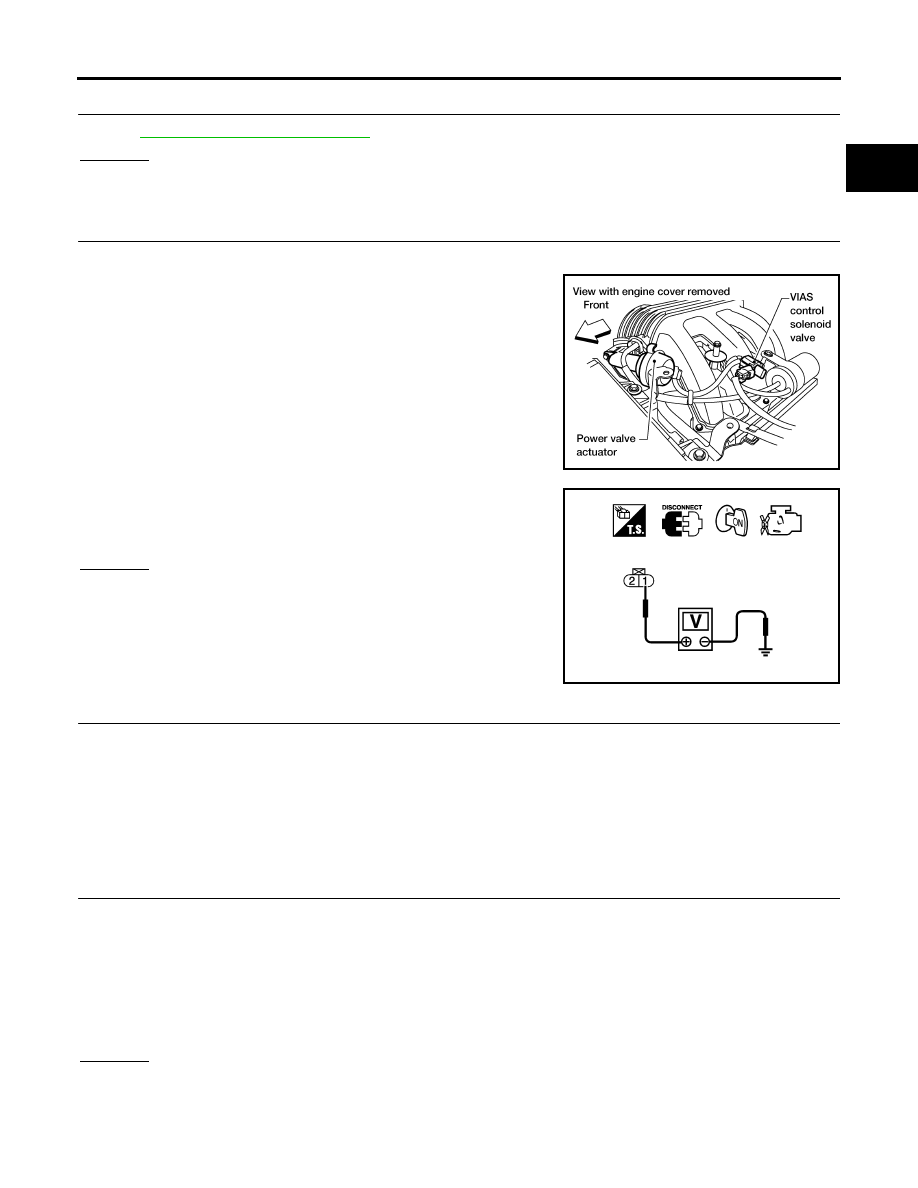
CHECK VIAS CONTROL SOLENOID VALVE POWER SUPPLY CIRCUIT

1.

Turn ignition switch OFF.

2.

Disconnect VIAS control solenoid valve harness connector.

3.

Turn ignition switch ON.

4.

Check voltage between terminal 1 and ground with CONSULT-II
or tester.

OK or NG

OK

>> GO TO 8.

NG

>> GO TO 7.

7. 

DETECT MALFUNCTIONING PART

Check the following.

Harness connectors E2, F32

Harness for open or short between VIAS control solenoid valve and IPDM E/R

Harness for open or short between VIAS control solenoid valve and ECM

>> Repair harness or connectors.

8. 

CHECK VIAS CONTROL SOLENOID VALVE OUTPUT SIGNAL CIRCUIT FOR OPEN AND SHORT

1.

Turn ignition switch OFF.

2.

Disconnect ECM harness connector.

3.

Check harness continuity between ECM terminal 29 and VIAS control solenoid valve terminal 2.
Refer to Wiring Diagram.

4.

Also check harness for short to ground and short to power.

OK or NG

OK

>> GO TO 9.

NG

>> Repair open circuit or short to ground or short to power in harness or connectors.

BBIA0569E

Voltage: Battery voltage

PBIB0173E

Continuity should exist.

EC-668

VIAS

2007 Pathfinder

9. 

CHECK VIAS CONTROL SOLENOID VALVE

Refer to 

EC-668, "Component Inspection"

  .

OK or NG

OK

>> GO TO 10.

NG

>> Replace VIAS control solenoid valve.

10. 

CHECK INTERMITTENT INCIDENT

Refer to 

EC-145, "TROUBLE DIAGNOSIS FOR INTERMITTENT INCIDENT"

  .

>> INSPECTION END

Component Inspection

UBS00KI4

VIAS CONTROL SOLENOID VALVE

 With CONSULT-II

1.

Reconnect harness connectors disconnected.

2.

Turn ignition switch ON.

3.

Perform “VIAS SOL VALVE” in “ACTIVE TEST” mode.

4.

Check air passage continuity and operation delay time under the
following conditions.

Operation takes less than 1 second.

 Without CONSULT-II

Check air passage continuity and operation delay time under the fol-
lowing conditions.

Operation takes less than 1 second.

VACUUM TANK

1.

Disconnect vacuum hose connected to vacuum tank.

2.

Connect a vacuum pump to the port (A) of vacuum tank.

3.

Apply vacuum and make sure that vacuum exists at the port (B).

Condition

VIAS SOL VALVE

Air passage continuity 

between (A) and (B)

Air passage continuity 

between (A) and (C)

ON

Yes

No

OFF

No

Yes

PBIB2505E

Condition

Air passage continuity 

between (A) and (B)

Air passage continuity 

between (A) and (C)

12V direct current supply 
between terminals 1 and 2

Yes

No

No supply

No

Yes

PBIB2532E

PBIB0846E

VIAS

EC-669

C

D

E

F

G

H

I

J

K

L

M

A

EC

2007 Pathfinder

Removal and Installation

UBS00KI5

VIAS CONTROL SOLENOID VALVE

Refer to 

EM-20, "INTAKE MANIFOLD"

  .

EC-670

MIL AND DATA LINK CONNECTOR

2007 Pathfinder

MIL AND DATA LINK CONNECTOR

PFP:24814

Wiring Diagram

UBS00KIY

BBWA2381E

MIL AND DATA LINK CONNECTOR

EC-671

C

D

E

F

G

H

I

J

K

L

M

A

EC

2007 Pathfinder

BBWA1780E

EC-672

SERVICE DATA AND SPECIFICATIONS (SDS)

2007 Pathfinder

SERVICE DATA AND SPECIFICATIONS (SDS)

PFP:00030

Fuel Pressure

UBS00KIZ

Idle Speed and Ignition Timing

UBS00KJ0

*: Under the following conditions:

Air conditioner switch: OFF

Electric load: OFF (Lights, heater fan & rear window defogger)

Steering wheel: Kept in straight-ahead position

Calculated Load Value

UBS00KJ1

Mass Air Flow Sensor

UBS00KJ2

*: Engine is warmed up to normal operating temperature and running under no load.

Intake Air Temperature Sensor

UBS00KJ3

Engine Coolant Temperature Sensor

UBS00KJ4

Air Fuel Ratio (A/F) Sensor 1 Heater

UBS00KJ5

Heated Oxygen sensor 2 Heater

UBS00KJ6

Crankshaft Position Sensor (POS)

UBS00KJ7

Refer to 

EC-361, "Component Inspection"

 .

Camshaft Position Sensor (PHASE)

UBS00KJ8

Refer to 

EC-370, "Component Inspection"

 .

Throttle Control Motor

UBS00KJ9

Fuel pressure at idling kPa (kg/cm

2

 , psi)

Approximately 350 (3.57, 51)

Target idle speed

No load* (in P or N position)

625 

±

 50 rpm

Air conditioner: ON

In P or N position

625 rpm or more

Ignition timing

In P or N position

15 

±

 5

°

 BTDC

Condition

Calculated load value% (Using CONSULT-II or GST)

At idle

5 - 35

At 2,500 rpm

5 - 35

Supply voltage

Battery voltage (11 - 14V)

Output voltage at idle

0.9 - 1.2*V

Mass air flow (Using CONSULT-II or GST)

2.0 - 6.0 g·m/sec at idle*

7.0 - 20.0 g·m/sec at 2,500 rpm*

Temperature 

°

C (

°

F)

Resistance k

25 (77)

1.800 - 2.200

Temperature 

°

C (

°

F)

Resistance k

20 (68)

2.1 - 2.9

50 (122)

0.68 - 1.00

90 (194)

0.236 - 0.260

Resistance [at 25

°

C (77

°

F)]

1.80 - 2.44

Resistance [at 25

°

C (77

°

F)]

9.9 - 13.3

Resistance [at 25

°

C (77

°

F)]

Approximately 1 - 15

SERVICE DATA AND SPECIFICATIONS (SDS)

EC-673

C

D

E

F

G

H

I

J

K

L

M

A

EC

2007 Pathfinder

Fuel Injector

UBS00KJA

Fuel Pump

UBS00KJB

Resistance [at 10 - 60

°

C (50 - 140

°

F)]

11.1 - 14.5

Resistance [at 25

°

C (77

°

F)]

0.2 - 5.0

EC-674

SERVICE DATA AND SPECIFICATIONS (SDS)

2007 Pathfinder


Content      ..     223      224      225      226     ..